background image

ENGLISH

FRANÇAIS

DEUTSCH

ESP

AÑOL

Р

OR

TUGUÊS

3

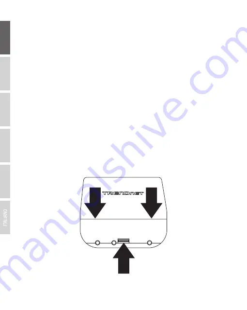
1. Remove the cover of the access point by pushing and holding the tab in the vertical direction 
  upward (based on the access point orientation below) and pulling the cover in the two 
  locations noted below away from the access point.

Pull and hold tab

Aside from the preconfigured WDS bridge settings, the TEW-740APBO access points will also be 
configured with the following default settings:

Verify connectivity between the two access points before mounting.


TEW-740APBO #1

    Mode: WDS Mode
     IP Address: 192.168.10.50
    Netmask (Subnet Mask): 255.255.255.0
    IP Gateway (Default Gateway): 192.168.10.1
    Primary DNS: 192.168.10.1


TEW-740APBO #2

    Mode: WDS Mode
     IP Address: 192.168.10.51
    Netmask (Subnet Mask): 255.255.255.0
    IP Gateway (Default Gateway): 192.168.10.1
    Primary DNS: 192.168.10.1

Содержание TEW-740APBO2K

Страница 1: ...Quick Installation Guide TEW 740APBO2K...

Страница 2: ...Table of Content 1 English 1 Before You Start 2 Hardware Setup and Configuration 3 Ground Wire and Pole Mount Installation...

Страница 3: ...injector that is supplied with the TEW 740APBO The RJ 45 Ethernet cable between the passive PoE injector and access point can have a maximum length of up to 60 m 197 ft Package Contents 2 x TEW 740APB...

Страница 4: ...the Ethernet ports and LEDs are located No additional configuration is required WIFI MAC XXXXXXXXXXXXXXXXX ETH LAN1 MAC XXXXXXXXXXXXXXXXX Model TEW 740APBO A S N XXXXXXXXXXXXXXX H W V2 0R FW 2 0K Made...

Страница 5: ...m the preconfigured WDS bridge settings the TEW 740APBO access points will also be configured with the following default settings Verify connectivity between the two access points before mounting TEW...

Страница 6: ...moved This will create the opening for a RJ 45 network cable to be routed through Tab 3 Using a network cable connect one end of the cable to the LAN PoE port and push the cable into the cable guide o...

Страница 7: ...gh the LED indicators 8 Assign a static IP address to your computer s network adapter in the subnet of 192 168 10 x e g 192 168 10 10 and subnet mask of 255 255 255 0 9 Using another network cable con...

Страница 8: ...and type in the following commands 11 Make sure both access points are powered on approximately 15 ft 5 m apart from one another with front of access points directly facing each other 15 ft 5m LAN1 Po...

Страница 9: ...connectivity test fails wait for about a minute and try again Make sure there are no obstacles between the two access points when running the connectivity test and make sure the two access points are...

Страница 10: ...he grounding point screw Then reattach the ground screw clockwise along with the grounding wire After installing the grounding wire remove another tab on the enclosure by gently bending back and forth...

Страница 11: ...rough the holes located at the back of the access point 4 Wrap the fasteners around the pole where the access points will be installed On the fasteners insert the open end into the locking mechanism a...

Страница 12: ...Quick Installation Reference 10 Building 1 Building 2 Internet Modem Router...

Страница 13: ...This product is herewith confirmed to comply with the Directives EN 300 328 V1 9 1 02 2015 EN 62311 2008 Safety EN 60950 1 2006 A11 2010 A12 2011 A2 2013 EMC EN 301 489 1 V1 9 2 09 2011 EN 301 489 17...

Страница 14: ...eristicas del adaptador de alimentac n necesario para su funcionamiento El uso de un adaptador distinto al mencionado puede producir da os fisicos y o da os al equipo conectado El adaptador de aliment...

Отзывы: