Traxxas Nitro Sport 4504 Скачать руководство пользователя страница 6

4

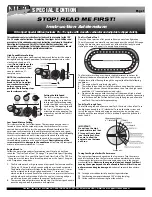
INSTALLING RECEIVER BATTERIES

The receiver battery holder is located underneath the bat-

tery cover. Remove the battery cover by removing the two
body clips from the posts on both sides of the battery holder.

Install 4 “AA” batteries into the battery holder. Alkaline batteries
should be used. Place the battery holder into the battery cover
with the cushioning foam. Secure the battery cover to the chassis
using the two body clips as shown.

ANTENNA SETUP

Locate the plastic tube and the antenna tip (supplied in the bag with
your instructions). Insert the black antenna wire, extending from the
receiver housing, into one end of the tube and push it all the way
through. Spray the wire with glass cleaner to make it easier to insert.

Insert the tube into the antenna mount in the side of the chassis.
Fold the remaining antenna wire over the top of the antenna tube
and secure it with the vinyl antenna tip.

Under no circumstances should you ever cut your antenna wire.
Its length is specially tuned to the frequency band, and cutting it
could severely shorten the radio’s range. On the transmitter, 

fully

extend

the chrome telescopic antenna.

RADIO SYSTEM OPERATION

Your radio system was pre-adjusted before it left the factory, however,
the adjustment should be checked prior to running the truck.

1) Before you ever turn your radio system on, you must “clear”

your frequency. There are six different channels numbered 1
through 6. Each of the six channels is represented by a color.
Look at the crystal in the back of the transmitter to determine
which of the channels your truck is operating on. Clearing your
frequency means checking to be sure that no one else in the
area is operating on the same channel.

2) 

TIP: Always turn the transmitter on first and off last.

This

will prevent the model from receiving stray signals and run-
ning out of control. Slide the transmitter switch to the “on”

position. A steady red light
should illuminate.

A flashing

red light indicates weak bat-
teries.

Weak batteries will limit

the range of the radio signal
between your transmitter and
receiver. Loss of the radio signal
can cause you to lose control of
the truck.

3) Turn the truck on. The switch is located on the chassis. The 

servos should jump and move to their idle (neutral) positions.

RADIO SYSTEM ADJUSTMENTS

• THROTTLE NEUTRAL ADJUST

The throttle neutral adjustment is located on the transmitter

face and controls the forward and reverse travel of the throttle
trigger. There are two settings, 50/50 which allows equal travel
for both forward and brake, and 70/30 which allows more travel
for throttle and less for brake. Change the adjustment by press-
ing the button and sliding it to the desired position. 70/30 is the
recommended setting while running the Nitro Sport.

• SERVO REVERSING SWITCHES

On the front of the transmitter there are two switches. One

for throttle and one for steering. Moving the switches reverses
the direction of the corresponding servos. For example, if you
turn your steering wheel right and the model moves left, then
switch the steering servo reversing switch to correct the servo
direction. You may need to adjust the corresponding trim control
after moving the servo-reversing switch.

TOTAL TRIGGER

MOVEMENT

50%

REVERSE

50%

FORWARD

Contact Traxxas for assistance: 1-888-TRAXXAS. 972-613-3300 (outside USA). E-Mail us at [email protected]

Содержание Nitro Sport 4504

Страница 1: ...turns out from closed on the low speed needle The mixtures were preset at the factory and should not be adjusted until after the engine is running and you are able to observe and evaluate the engine s...

Страница 2: ...hile still maintaining reliable running characteristics 4 Reset the throttle trim on the transmitter Fine Tuning the Carburetor After fine tuning your engine at the end of the break in procedure no ma...

Страница 3: ...OPERATING INSTRUCTIONS COVERS MODELS 4504 AND 4510...

Страница 4: ...is usually purchased by the gallon or quart so a smaller bottle with a dispensing tube is required to fill the fuel tank The fuel tank in the Nitro Sport has a capacity of 75cc The fuel bottle should...

Страница 5: ...a 27 MHZ FREQUENCY BAND CHANNEL The 27 MHZ FREQUENCY BAND is divided into 6 CHANNELS so that up to six cars can be operated simultaneously These CHANNELS are referred to by their number and flag colo...

Страница 6: ...k is operating on Clearing your frequency means checking to be sure that no one else in the area is operating on the same channel 2 TIP Always turn the transmitter on first and off last This will prev...

Страница 7: ...GINE STEP 1 INSTALL THE AIR FILTER Remove the protective cap from the carburetor air intake Install the rubber air filter base and pre lubed foam element onto the car buretor intake The foam air filte...

Страница 8: ...rformance and fouled glow plugs Don t give up on it These are just break in pains that every new engine has to go through They will disappear once you get through the break in period Just keep it runn...

Страница 9: ...mechanical limits Leaning the fuel mixture beyond the safe allowable limits will result in poor performance and engine damage After the fourth tank of fuel the break in process should be com plete No...

Страница 10: ...g up the inside rear wheel in hard turns then stiffen the front suspension If it picking up the inside front wheel in hard turns then stiffen the rear suspension Proper set up will add stability and h...

Страница 11: ...504 Before installing the radio system center your servos as described in your radio system s operating instructions Note the plug on the Traxxas 4 cell battery holder is compatible with Traxxas and F...

Страница 12: ...onnect the EZ Start motor Do not prime the engine Partially open the throttle and press the EZ Start button The engine should start immediately GLOW PLUGS The glow plug in your engine is a consumable...

Страница 13: ...speed set too low Increase idle speed page 7 28 Fuel flow blocked Check that all fuel lines are clear with no pin hole leaks Check for dirt blockage in the carburetor fuel inlet and high speed needle...

Страница 14: ...assembly Use a 5 16 inch nut driver to remove the glow plug and copper gasket STEP 10 Use a 2 5mm allen wrench to remove the four 3x12mm cap head screws that fasten the cylinder head Rock the cylinder...

Страница 15: ...the wrist pin also Rinse thoroughly with dena tured alcohol and lube with after run oil STEP 13 Pull the sleeve straight up and out of the crankcase If the sleeve will not move rotate the crankshaft u...

Страница 16: ...ee step 14 STEP 25 To assemble the connecting rod and piston place a drop of caster oil in the top end of the connecting rod Insert the wrist pin through the piston and the top of the connecting rod S...

Отзывы: