Traxxas E Revo 5603 Скачать руководство пользователя страница 28

28 • E-Revo

This advanced tuning guide will take you one step further into the 
cutting edge technology that has been designed into E-Revo. Follow 
the instructions provided here to take advantage of E-Revo’s maximum 
performance potential. 

SUSPENSION AND ALIGNMENT SETTINGS
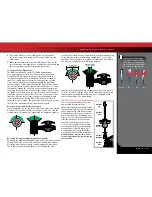
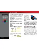
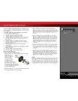
Caster Adjustment

The caster angle of the front 
suspension may be used to adjust 
the understeer (push)/oversteer 
handling characteristics of the 
model. Generally, increasing the 
caster angle will move the truck 
towards an oversteer condition 
(more traction on the front tires, less 
on the rear tires). Decreasing the 
caster angle will create a tendency 
towards understeer (pushing in the 
turns). From the factory, the front 
suspension is set to a caster angle of 
10-degrees. The rear caster angle is 
not adjustable. The caster angle 
of the front suspension can be 
adjusted from 5° to 15°. Adjust 
the caster by positioning the 
caster adjustment shims on the 
upper control arms of the front 
suspension as shown in the 
table to the right.

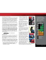
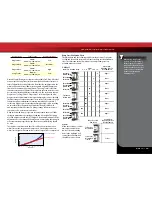
Caster Angle, and Bump Steer

Bump steer is unwanted change in the steering angle of the front wheels  
as the suspension travels up and down. It can result in unstable and 
unpredictable handling. Bump steer is affected by the position of the 
outer toe link end on the axle carrier. From the factory, the toe links are 
positioned so that bump steer is virtually eliminated (about 3/100 of 
a degree through the entire range of travel). When the caster angle is 
changed, the outer toe link end should be repositioned on the axle carrier 
to maintain zero bump steer geometry. Adjustment is achieved using the 
shims and hollow balls provided with the vehicle. Refer to the Bump Steer 
Elimination chart on page 29,  and look up your caster angle setting to 
find the correct position for the outer toe links. Positioning the toe-links 
correctly will maintain the original factory geometry and eliminate the 
unwanted steering angle changes caused by bump steer.
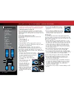
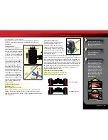
Roll Center

There are two holes on the 
bulkheads to mount each upper 
suspension arm. The roll center 
of the vehicle can be raised by 
mounting the upper control arm in 
the lower of the two holes. This will 
effectively increase the roll stiffness 
of the vehicle (similar to installing 
swaybars). Adding roll resistance to 
one end of the vehicle will tend to 
add traction to the opposite end. For example, increasing roll resistance in 
the rear by installing the upper arms in the lower holes will provide more 
traction for the front wheels and potentially more steering. Installing the 
upper arms in the lower holes on the front and rear will increase overall 
roll resistance without changing the handling balance. The arms are 
installed in the upper position from the factory to make the truck easier 
and more forgiving to drive and less likely to traction roll in turns. The 
lower holes should be reserved for track tuning. 

Note:

 When the upper 

suspension arms are moved to the lower holes, the front outer toe link 
ends and the rear toe control links should be repositioned to eliminate 
bump steer. Refer to the Bump Steer Elimination chart on page 29, 
and look up your suspension combination (caster angle and roll center 
position) to find the correct position for the front outer toe links and the 
rear toe control links. Adjustment is achieved using the shims and hollow 
balls provided with the vehicle.

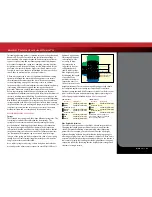
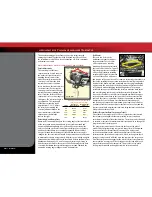
Rockers (Progressive Rate/ Suspension Travel)

One of the most exciting aspects of E-Revo’s suspension is the inboard 
shock (damper) arrangement that uses pivoting rockers to translate 
vertical wheel travel into linear shock motion. The rockers can be changed 
to increase or decrease the maximum wheel travel and also to change the 
progressive rate of the suspension. 
The progressive rate determines how much the force at the wheel 
produced by the springs being compressed (wheel force) will vary with 
suspension travel (or vertical travel of the wheel). On a progressive 
suspension arrangement, the wheel force will increase at a faster and 
faster rate as the suspension is compressed. It feels as though the shock 
spring gets progressively stiffer the more you compress the suspension. 
On a linear suspension arrangement, the wheel force increases linearly as 
the suspension is compressed. The spring does not feel any stiffer, even 
when the suspension is fully compressed. This provides a very “plush” 
feeling suspension with seemingly bottomless suspension travel.

Caster adjustment shims (2 front, 2 rear)

Vertical

Ground plane

10°

Upper Control Arm

Upper Mounting Holes

Upper Control Arm

Lower Mounting Holes

Caster

In Front of 

Hinge Pin Boss

Behind Hinge 

Pin Boss

5.0°

None

Four

7.5°

One

Three

10.0°

Two

Two

12.5°

Three

One

15.0°

Four

None

Number & Position of Caster Adjustment 

Shims (Front Upper Control Arm)

ADVANCED TUNING ADJUSTMENTS

Содержание E Revo 5603

Страница 1: ...MODEL 5603 owners manual...

Страница 2: ...t it is backed by a team of professionals who aim to provide the highest level of factory support possible Traxxas models are about experiencing total performance and satisfaction not just with your m...

Страница 3: ...at Traxxas com You may also e mail customer support with your question at support Traxxas com Join thousands of registered members in our online community at Traxxas com Traxxas offers a full service...

Страница 4: ...from the electronic speed control when the model is not in use and when it is being stored or transported Allow the battery packs to cool off between runs before charging Children should have responsi...

Страница 5: ...ge 11 A peak detecting charger is recommended for best performance and longest battery life For more information see Use the Right Charger on page 12 Warning LithiumPolymer LiPo batteriesshouldnotbeus...

Страница 6: ...b Rear Suspension Arm Axle Carrier Pivot Ball Toe Link Turnbuckle Receiver Box Light Pipe Skid Plate Steering Servo Steering Servo Front Body Mount Battery Compartment Door Battery Compartment Vent El...

Страница 7: ...The transmitter requires 4 AA alkaline or rechargeable batteries Follow these critical steps to maintain the performance of your model and keep it in excellent running condition 4 Install battery pac...

Страница 8: ...the electronic motor control inside the model The EVX 2 uses MOSFET power transistors to provide precise digital proportional throttle control Electronic speed controls use power more efficiently tha...

Страница 9: ...sure that is forcing the water through the hose 550 and 540 These numbers refer to the size of the motor 550 motors have armatures that are 30 longer than 540 motors IMPORTANT radio system Precautions...

Страница 10: ...DIAGRAM 1 6 8 V E S C W A T E R P R O O F Not Used TQ 2 4GHz Transmitter Antenna Steering Trim Multi Function Knob Throttle Trigger Throttle Neutral Adjust Steering Wheel Power Switch Battery Compart...

Страница 11: ...r tab This is adjustable to fit a variety of battery sizes We recommend using this combination for all NiMH batteries Make sure to adjust the battery retainer tab to keep your battery pack snug agains...

Страница 12: ...pring Clip Removal 1 Pull down on the inside of the clip 2 Push the clip in toward the center of the model to release Spring Clip Installation 1 Insert the two tabs on the spring clip into the rectang...

Страница 13: ...til you become familiar with all the adjustments and capabilities of your model To change the throttle neutral adjust position turn the transmitter off before adjusting the neutral position You will n...

Страница 14: ...up and then walk away from the model with the transmitter until you reach the farthest distance you plan to operate the model 4 Operate the controls on the transmitter once again to be sure that the...

Страница 15: ...ering Sensitivity Negative Exponential By turning the Multi Function knob clockwise the steering sensitivity of the model will be decreased Note that a relatively large amount of steering wheel travel...

Страница 16: ...e full throttle position and hold it there B 6 When the LED blinks RED TWICE Push the throttle trigger to the full reverse and hold it there C 7 When the LED turns solid GREEN programming is complete...

Страница 17: ...Profile numbers 3 When the light blinks red once release the EZ Set button 4 The light will then turn green and the model is ready to drive Selecting Race Mode Profile 2 1 Connect two fully charged b...

Страница 18: ...t pack Because of the wide variation in the types of batteries that are available and the methods with which they can be charged it s impossible to give exact run times for the model Another major fac...

Страница 19: ...h higher loads on the motors Motor Precautions Titan motor life can be greatly reduced in mud and water If the motors get excessively wet or submerged use very light throttle run the motors slowly unt...

Страница 20: ...ty to maintain a watertight seal in the box The patent pending wire clamp feature gives you the ability to also install aftermarket radio systems and maintain the watertight features of the receiver b...

Страница 21: ...recommended for advanced users SUSPENSION TUNING Springs The front and rear springs on E Revo have different spring rates The rear springs are about 20 stiffer than the front springs The spring s pre...

Страница 22: ...k Oil The 4 oil filled aluminum shocks dampers effectively control the suspension movement by preventing the wheels and tires from continuing to bounce after rebounding from a bump Changing the oil in...

Страница 23: ...ravel Static camber is the camber angle at the wheel when the vehicle is set at its normal stationary ride height The suspension pivot balls located in the axle carriers adjust the static camber The p...

Страница 24: ...g the spring loaded locknut on the slipper shaft Use the supplied universal wrench To tighten or loosen the slipper nut insert the 2 0mm hex wrench into the hole in the end of the slipper shaft This l...

Страница 25: ...ed incorrectly is not recommended as this will reduce efficiency performance and cause premature motor failure Using two of the same part number motors in not recommended Only use the correct motors i...

Страница 26: ...cedure If necessary fine tune the length of the second steering link to eliminate any load on the steering system in the neutral position If you are using aftermarket servos it is important to use ser...

Страница 27: ...Motors Every 10 15 runs remove clean and lubricate the motors Use a product such as electric motor cleaning spray to flush dirt out of the motors After cleaning lubricate the bushings at each end of t...

Страница 28: ...will tend to add traction to the opposite end For example increasing roll resistance in the rear by installing the upper arms in the lower holes will provide more traction for the front wheels and pot...

Страница 29: ...ct of the various rocker arms on wheel force as the suspension is compressed On the progressive rate wheel force is light at first and increases as the suspension is compressed Bump Steer Elimination...

Страница 30: ...e top of the shock body Slowly move the piston up and down always keeping it submerged in oil to release the air bubbles Let the shock sit for a few minutes to allow any remaining air bubbles to surfa...

Страница 31: ...d with extra transmission and driveline strength to make it capable of handling extreme brushless power One or two brushless motors may be used A specially designed motor plate part 5690X and gear cov...

Страница 32: ...oint adjustment settings you select will represent what you wish to be the servo s maximum travel the Steering Percentage or Braking Percentage functions will not override the End Point settings Steer...

Страница 33: ...repeatedly 4 Press SET once The status LED will blink green once repeatedly 5 Press MENU once The status LED will blink green twice repeatedly 6 Press SET The memory is now selected to be deleted Pre...

Страница 34: ...save Push forward to desired endpoint and press set to save To reset max throw Let go of controls and press SET The menu tree below shows how to navigate through the TQ 2 4GHz transmitter s various s...

Страница 35: ...MENU twice red LED blinks x3 THROTTLE TRIM 100 100 0 0 Turn steering wheel to desired max left and right travel x8 Press SET to save each position THROTTLE TRIM 100 100 0 0 Turn steering wheel to tes...

Страница 36: ...1100 Klein Road Plano Texas 75074 1 888 TRAXXAS 091216 KC1253 R01 owners manual MODEL 5603...

Отзывы: