background image

32 • E-REVO VXL BRUSHLESS

ADVANCED TUNING ADJUSTMENTS

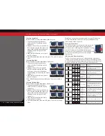
SHOCK TUNING

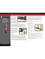
Shock Pistons

The shock pistons can be replaced 
with the available optional pistons 
to vary the amount of damping. 
Optional pistons with bypass holes 
that are larger or smaller (1, 2, or 
3) than the factory installed stock 
pistons can be used to decrease 
or increase damping respectively. 
Change the pistons if you only have 
one weight of shock oil available 
to you. From the factory, E-Revo is 
equipped with #2 pistons in the front 
and rear.

Shock disassembly

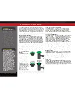
The shocks must be removed from
the vehicle and disassembled to 
change the pistons. Use the shock 
exploded views included with the 
model to aid in the assembly process.
1.   Remove the spring and lower  

spring retainer from the shock. 

2.   Remove the shock cap (A) and 

empty the shock body of shock oil. 

3.  Remove the lower cap (B) and  

the X-ring from the shock body. 

4.   Use side cutters to grip the shock 

shaft just above the rod end (C). 
Remove the rod end from the shock shaft using the suspension multi-
tool (C). 

5.   Remove the shock shaft with piston from the shock body  

out through the top of the shock body. 

Shock assembly

1.   Replace the stock piston with desired 

optional piston. Be careful not to lose the 
small washer located below the piston.

 2.   Position the new piston onto the shock shaft 

above the small washer. Grip the threads 
of the shaft with side cutters or needlenose 

pliers and tighten the nut with a 4-way wrench to secure the 
assembly.

3.    Insert the shock shaft assembly through the shock body until the 

piston bottoms out. 

4.   Lubricate the shaft and X-ring with silicone oil. 
5.   Install the X-ring over the shaft and into the bore of the shock body. 
6.   Install the lower cap using the suspension multi-tool (B). 
7.   Slide the bump stop onto the shaft. 
8.   Grip the shaft close to the threads with needle nose pliers or side 

cutters and thread the rod end onto the shock shaft until the rod 
end bottoms out (C).

9.   Fill the shock with new silicone shock oil up to the top of the  

shock body. Slowly move the piston up and down (always keeping 
it submerged in oil) to release the air bubbles. Let the shock sit for a 
few minutes to allow any remaining air bubbles to surface.

10.  Slowly thread the upper cap with the installed shock bladder onto 

the shock body with the suspension multi-tool (A). The excess oil will 
bleed out of the small hole in the shock cap. Tighten the shock cap 
until snug. Use a flat wrench to hold onto the shock body while 
tightening. 

11.  Reinstall the spring and lower retainer. 

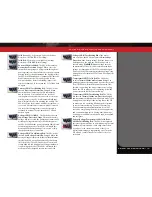
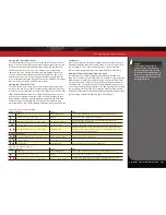
Tuning The Sealed Gear Differentials

E-Revo’s front and rear gear differentials allow the left and right  
wheels to spin at different speeds while turning so that the tires do  
not scuff or skid. This decreases the turning radius and increases  
steering performance. 
The performance of the differentials can be tuned for different driving 
conditions and performance requirements. The differentials are filled 
with silicone differential fluid, and are sealed to maintain consistent 
long-term performance. Changing the oil in the differential with either 
lower or higher viscosity oil will vary the performance characteristics of 
the differentials. Changing to a higher viscosity oil in the differential will 
reduce the tendency for engine power to be transferred to the wheel 
with the least traction. You may notice this when making sharp turns 
on slick surfaces. The unloaded wheels on the inside of the turn have 
the least traction and tend to spin up to extremely high rpms. Higher 
viscosity (thicker) oil causes the differential to act like a limited-slip 
differential, distributing more equal power to the left and right wheels. 
E-Revo will generally benefit from higher viscosity oil when climbing, 
rock crawling, or racing on low traction surfaces. 

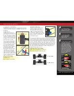
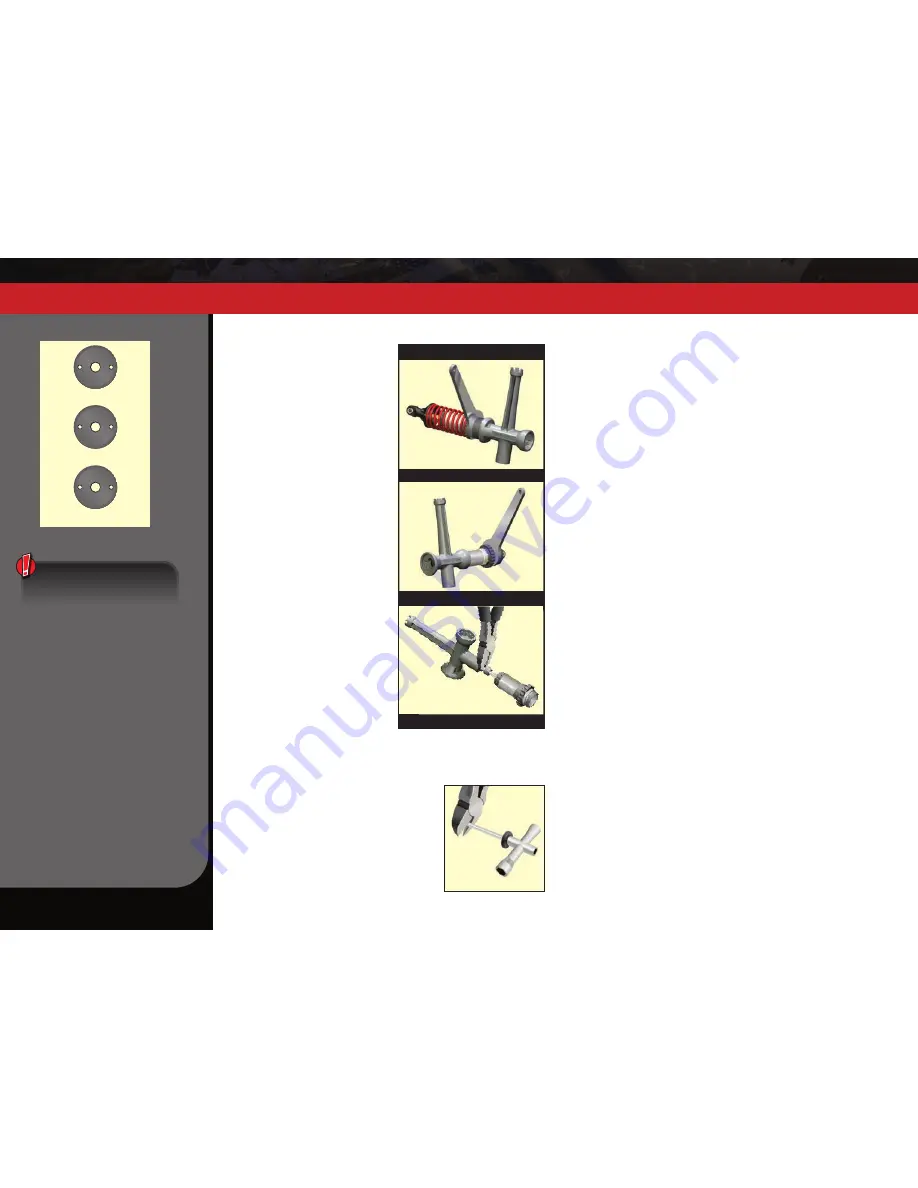
A. Tighten/Loosen Upper Cap

C. Remove/Install Rod End

B. Tighten/Loosen Lower  Cap

Multi-tool Shock Functions

Piston Installation/Removal

2

2

2

1

1

1

3

3

3

Shock Piston Hole Sizes

Piston 1: 1.10 mm

Piston 2: 1.00 mm

Piston 3: 0.95 mm

Never slide the threads on 
the shock rod past the X-ring 
seal when it is installed and 
compressed by the bottom 
cap of the shock. Doing so will 
damage the seal and cause 
shock oil to leak.

Содержание 86086-4

Страница 1: ...MODEL 86086 4 OWNER S MANUAL...

Страница 2: ...ontact us and what your support options are Quick Start This manual is designed with a Quick Start path that outlines the necessary procedures to get your model up and running in the shortest time pos...

Страница 3: ...run Warnings Helpful Hints Cross References Throughout this manual you ll notice warnings and helpful hints identified by the icons below Be sure to read them An important warning about personal safe...

Страница 4: ...No Schottky Diodes External Schottky diodes are not compatible with reversing speed controls Using a Schottky diode with your Traxxas speed control will damage the ESC and void the 30 day warranty Alw...

Страница 5: ...ximum manufacturer recommended charge rate DO NOT attempt to charge non rechargeable batteries explosion hazard batteries that have an internal charge circuit or a protection circuit or batteries that...

Страница 6: ...Ultra Premium Tire Glue part 6468 CA glue Hobby knife Side cutters and or needle nose pliers Soldering iron For more information on batteries see Use the Right Batteries on page 12 Battery and charger...

Страница 7: ...iveshaft Steering Link Toe Link Electronic Speed Control Battery Door Release Tab Hex Hub Pivot Ball Push Rod Push Rod Rocker Rocker Skid Plate Spring Pre load Adjuster Transmission Axle Carrier Chass...

Страница 8: ...tance and that there is no interference from outside sources 3 Install batteries in the transmitter See page 12 8 Detail your model See page 9 The transmitter requires 4 AA alkaline batteries sold sep...

Страница 9: ...and servos to be powered by the main battery pack in an electric model This eliminates the need to carry a separate pack of 4 AA batteries to power the radio equipment Brushless Motor A D C brushless...

Страница 10: ...or sensors and wiring are not required Servo Small motor unit in your model that operates the steering mechanism Solder Tabs Accessible external contacts on the motor that allows for easy wire replace...

Страница 11: ...utral Adjust Steering Wheel Power Switch Battery Compartment Set Button Menu Button Red Green Status LED see page 35 for more info Link Button LED Sensor Expansion Port Accessory sensor expansion port...

Страница 12: ...n light If the status LED flashes red the transmitter batteries may be weak discharged or possibly installed incorrectly Replace with new batteries The power indicator light does not indicate the char...

Страница 13: ...toward the rear of the truck When using the battery retainers in the front of the battery compartment use two 3x10 countersunk cap screws to retain each battery retainer Do not use the battery retaine...

Страница 14: ...ttle trigger Change the adjustment by pressing the button and sliding it to the desired position There are two settings available 50 50 Allows equal travel for both acceleration and reverse 70 30 Allo...

Страница 15: ...ach the farthest distance you plan to operate the model 4 Operate the controls on the transmitter once again to be sure that the model responds correctly 5 Do not attempt to operate the model if there...

Страница 16: ...om the factory When reinstalling the antenna first slide the antenna wire into the bottom of the antenna tube until the white tip of the antenna is at the top of the tube under the black cap Insert th...

Страница 17: ...ee blinks Training Mode will slow the model down by 50 to make it easier for new drivers to control the model 3 Release the EZ Set button after the number of blinks for the mode you wish to select Not...

Страница 18: ...ton is released and a mode is selected Accessory Power Panel The VXL 6s electronic speed control is equipped with a power panel that can be used to power optional accessories such as LED light kits or...

Страница 19: ...he VXL 6s will automatically shut down fail safe mode The LED on the speed control will slowly blink red indicating a low voltage shutdown Stop driving the model The VXL 6s will stay in this mode unti...

Страница 20: ...tightened About Run Time A large factor affecting run time is the type and condition of your batteries The milliamp hour mAh rating of the batteries determines how large their fuel tank is A 3000mAh...

Страница 21: ...hen remove the cut material for an approximately 3mm or 1 8 diameter hole Repeat on the opposite side of the tire 180 apart Cover the two breather holes in the wheel with adhesive tape Motor Precautio...

Страница 22: ...to also install aftermarket radio systems and maintain the watertight features of the receiver box Removing the Receiver 1 To remove the cover remove the two 3x8mm button head cap screws 2 To remove...

Страница 23: ...s pre load tension can be adjusted by turning the spring pre load adjuster Adjusting the pre load changes the suspension sag Suspension sag basically defines how much the suspension compresses when th...

Страница 24: ...fect Changing the oil to a higher viscosity oil will increase damping Lowering the viscosity of the oil will cause the suspension damping to be reduced Damping should be increased with higher viscosit...

Страница 25: ...ide height The suspension pivot balls located in the axle carriers adjust the static camber The pivot balls are protected by blue dust plugs To adjust your static camber insert the supplied 2 5 mm hex...

Страница 26: ...ded tires on the model listed in your parts list Experimentation with different types of tires is recommended to see which ones work the best on the terrain where the model is run When selecting tires...

Страница 27: ...er You should be able to run a fresh strip of paper through the gears without binding them BASIC TUNING ADJUSTMENTS Gearing Compatibility Chart The chart below shows recommended gear combination range...

Страница 28: ...rvo horn 7 Position the steering servo saver arm perpendicular to the centerline of the vehicle 8 While holding the steering servo saver arm in the position mentioned in step 6 install the servo horn...

Страница 29: ...ure silicone shock oil to prolong the life of the seals If you are experiencing leakage around the top of the shock inspect the bladder in the top cap for signs of damage or distortion from overtighte...

Страница 30: ...l resistance to one end of the vehicle will tend to add traction to the opposite end For example increasing roll resistance in the rear by installing the upper arms in the lower holes will provide mor...

Страница 31: ...e height then the next stiffer spring should be used The chart below demonstrate the effect of the various rocker arms on wheel force as the suspension is compressed On the progressive rate wheel forc...

Страница 32: ...he shock body Slowly move the piston up and down always keeping it submerged in oil to release the air bubbles Let the shock sit for a few minutes to allow any remaining air bubbles to surface 10 Slow...

Страница 33: ...kward off the post The motor mount was carefully engineering to provide additional features and adjustability Two sets of holes are provided for use with aftermarket motors These use 3mm screws with 2...

Страница 34: ...l the amount percentage of servo travel applied to steering Turning the Multi Function knob fully clockwise will deliver maximum steering throw turning the knob counterclockwise reduces steering throw...

Страница 35: ...ings made with the Multi Function knob are overlaid on top of each other For example if you assign the Multi Function to adjust Steering Percentage and set it for 50 then reassign the knob to control...

Страница 36: ...ve to select any model from a list of model memory entries The transmitter and receiver do it all for you automatically To activate Model Lock 1 Switch on the transmitter and receiver you wish to lock...

Страница 37: ...the TQi transmitter s various settings and functions Press and hold MENU to enter the Menu Tree and use the following commands to navigate through the menu and select options MENU When you enter a men...

Страница 38: ...s SET green LED blinks Press SET red LED blinks x3 Press MENU twice red LED blinks x3 Turn steering wheel to desired max left and right travel x8 Press SET to save each position Turn steering wheel to...

Страница 39: ...mums or averages Use the recording function to document your dashboard view with sound so that you can keep your eyes on your driving and not miss a single apex Manage up to 30 Models with Traxxas Lin...

Страница 40: ...6250 Traxxas Way McKinney TX 75070 1 888 TRAXXAS 180420 86086 4 OM EN R00 OWNER S MANUAL MODEL 86086 4...

Отзывы: