Travelmate P214-52 Скачать руководство пользователя страница 67

1-67

Machine Maintenance Procedures

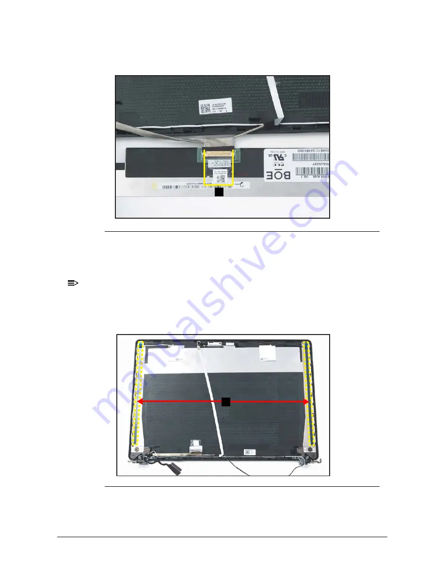
4. Adhere the mylar tape (C) to secure the eDP cable to the LCD panel (

Figure 1-77

).

Figure 1-77. Replacing the LCD Panel

5. Adhere the double-sided adhesive mounting tapes (A) on both sides of the LCD 

hinges and press each tape for about 30 seconds. Then peel off the protective film 
from the double-sided adhesive mounting tapes (

Figure 1-78

).

NOTE:

NOTE

:

Before applying the new double-sided adhesive mounting tapes, make sure to 
clean the surface properly with the rubbing alcohol. Then attach the adhesive 
mounting tapes onto the designated slots as shown in the below illustration 
(

Figure 1-78

).

Figure 1-78. Replacing the LCD Panel

C

A

Содержание P214-52

Страница 1: ...TravelMate P214 52 P214 52G RECYCLE GUIDE...

Страница 2: ...out the prior written permission of Acer Incorporated Disclaimer The information in this guide is subject to change without notice There are no representations or warranties either expressed or implie...

Страница 3: ...ocess names are shown in italics Example the DRS5 User s Guide usr local bin fd the TPH15spool_M program Computer output text that represents information displayed on a computer screen such as menus p...

Страница 4: ...red in this generic service guide In such cases contact the regional offices or the responsible personnel channel to provide further technical details When ordering FRU parts Check the most up to date...

Страница 5: ...2 USB Board Removal 1 35 Mainboard Removal 1 37 Speaker Module Removal 1 42 Top Assembly Removal 1 43 LCD Module Disassembly Process 1 44 LCD Module Disassembly Flowchart 1 44 LCD Bezel Removal 1 45 L...

Страница 6: ...84 Replacing the SSD Solid State Drive Module 1 87 Replacing the Heatsink 1 89 Replacing the Fan Module 1 91 Replacing the DIMM Dual In line Memory Module 1 93 Replacing the WLAN Wireless Local Area N...

Страница 7: ...may not represent the final product color or configuration Cable paths and positioning may also differ from the actual model During the removal and installation of components make sure all available...

Страница 8: ...edures 1 Place the system on a stable work surface 2 Remove AC adapter A from the system and peripherals Figure 1 1 3 Remove all cables from system Figure 1 1 AC Adapter Outlet 4 Remove the SD card fr...

Страница 9: ...disassembly sequence Observe the order of the sequence to avoid damage to any of the hardware components For example when removing the heatsink remove first the base cover battery and fan module in th...

Страница 10: ...ase Cover Removal M2 5 x 5 2 12 WLAN Module Removal M2 0 x 3 0 1 86 GDEN7 001 Fan Module Removal M2 5 x 4 0 2 86 RYYN7 001 Heatsink Removal M2 0 x 3 0 3 86 GDEN7 001 SSD Module Removal M2 0 x 3 0 1 86...

Страница 11: ...t the keyboard is damaged replace the entire top assembly HDD Module Removal M2 5 x 4 0 4 86 RYYN7 001 M3 0 x 3 5 4 86 TDY07 003 Touchpad Module Removal M2 0 x 3 0 2 86 GDEN7 001 LCD Module Removal M2...

Страница 12: ...from the base cover Figure 1 3 Figure 1 3 Base Cover Removal 2 Carefully pry up the base cover starting from the upper side near the LCD hinges to release the latches Then continue releasing the rema...

Страница 13: ...1 13 Machine Maintenance Procedures 3 Grasp and remove the base cover from the system Figure 1 5 Figure 1 5 Base Cover Removal ID Size Torque Quantity Screw Type Red Call out M2 5 5 2 3 0 15 kgf cm 12...

Страница 14: ...nd the battery pack A in the system Figure 1 6 2 Detach the adhesive tape B from the battery cable connector Figure 1 6 Figure 1 6 Battery Pack Removal 3 Disconnect the battery cable from the mainboar...

Страница 15: ...1 15 Machine Maintenance Procedures 4 Remove the battery pack from the system Figure 1 8 Figure 1 8 Battery Pack Removal IMPORTANT Follow local regulations for battery disposal...

Страница 16: ...Find the WLAN module A on the top assembly Figure 1 9 Figure 1 9 WLAN Module Location 2 Disconnect the AUX antenna white color from the WLAN AUX pin Figure 1 10 3 Disconnect the MAIN antenna black col...

Страница 17: ...ule in place Figure 1 10 Figure 1 10 WLAN Module Removal 6 Remove the WLAN module from the mainboard connector B Figure 1 11 Figure 1 11 WLAN Module Removal ID Size Torque Quantity Screw Type Red Call...

Страница 18: ...ures 1 18 DIMM Dual In line Memory Module Removal 0 Prerequisite Battery Pack Removal 1 Find the DIMM module A in the system Figure 1 12 2 Push the DIMM module clips B outwards Figure 1 12 Figure 1 12...

Страница 19: ...19 Machine Maintenance Procedures 3 Remove the DIMM module from the mainboard connector C Figure 1 13 Figure 1 13 DIMM Module Removal 4 Repeat steps 2 and 3 for an additional DIMM module if necessary...

Страница 20: ...n module A on the top assembly Figure 1 14 2 Disconnect the fan cable from the mainboard connector B Figure 1 14 3 Remove two 2 screws securing the fan module in place Figure 1 14 Figure 1 14 Fan Modu...

Страница 21: ...1 21 Machine Maintenance Procedures ID Size Torque Quantity Screw Type Red Call out M2 5 4 0 3 0 15 kgf cm 2...

Страница 22: ...eatsink Removal 0 Prerequisite Battery Pack Removal 1 Remove three 3 screws securing the CPU heatsink in place Figure 1 16 Figure 1 16 Heatsink Removal 2 Remove the heatsink A from the mainboard Figur...

Страница 23: ...1 23 Machine Maintenance Procedures ID Size Torque Quantity Screw Type Red Call out M2 0 3 0 2 0 10 kgf cm 3...

Страница 24: ...ve Module Removal 0 Prerequisite Battery Pack Removal 1 Remove one 1 screw securing the SSD module A in place Figure 1 18 Figure 1 18 SSD Module Removal 2 Remove the SSD module from the mainboard conn...

Страница 25: ...1 25 Machine Maintenance Procedures ID Size Torque Quantity Screw Type Red Call out M2 0 3 0 2 0 10 kgf cm 1...

Страница 26: ...LAN antenna cables B from the WLAN module connectors Figure 1 20 2 Detach the adhesive tape A from the mainboard Figure 1 20 3 Remove four 4 screws C securing the HDD bracket Figure 1 20 Figure 1 20 H...

Страница 27: ...5 Disconnect the HDD cable from the HDD module connector E Figure 1 22 Figure 1 22 HDD Module Removal 6 Remove four 4 screws F from the HDD bracket Figure 1 23 Figure 1 23 HDD Module Removal 7 Remove...

Страница 28: ...Machine Maintenance Procedures 1 28 ID Size Torque Quantity Screw Type C M2 5 4 0 3 0 15 kgf cm 4 F M3 0 3 5 3 0 15 0 kgf cm 4...

Страница 29: ...for easy access to the touchpad module connector Figure 1 24 2 Disconnect the touchpad FFC B from the mainboard connector and from the touchpad board connector Figure 1 24 Figure 1 24 Touchpad Module...

Страница 30: ...off and remove the touchpad conductive tape C from the touchpad module and top assembly Figure 1 25 Figure 1 25 Touchpad Module Removal 4 Remove two screws securing the touchpad module in place Figure...

Страница 31: ...e hand is placed underneath the touchpad module push the touchpad module slightly to disengage it from the bottom latches E and then remove the touchpad module F from the top assembly Figure 1 27 Figu...

Страница 32: ...from the WLAN module connectors Figure 1 28 2 Unroute the WLAN antenna cables from the guides on the top assembly Figure 1 28 3 Disconnect the eDP cable from the mainboard connector B Figure 1 28 Figu...

Страница 33: ...flat surface top assembly facing up Figure 1 30 6 Lift the top assembly until it is fully open Figure 1 30 Figure 1 30 LCD Module Removal 7 Close the top assembly and lift both LCD hinges until they a...

Страница 34: ...backwards to remove the top assembly away from the LCD module Figure 1 32 CAUTION Make sure all cables and antennas are moved away from the device to avoid damage during removal Figure 1 32 LCD Modul...

Страница 35: ...sconnect the USB board FFC A from the mainboard and USB board connectors Figure 1 33 2 Remove two 2 screws securing the USB board in place Figure 1 33 Figure 1 33 USB Board Removal CAUTION USB board F...

Страница 36: ...Machine Maintenance Procedures 1 36 3 Remove the USB board B from the top assembly Figure 1 34 Figure 1 34 USB Board Removal ID Size Torque Quantity Screw Type Red Call out M2 5 4 0 2 0 10 kgf cm 2 B...

Страница 37: ...N Wireless Local Area Network Module Removal DIMM Dual In line Memory Module Removal Fan Module Removal Heatsink Removal and SSD Solid State Drive Module Removal 1 Remove two 2 screws A securing the r...

Страница 38: ...es 1 38 2 Lift the top assembly until it is fully open Figure 1 36 Figure 1 36 Mainboard Removal 3 Close the top assembly and lift the right side of LCD hinge until it is fully extended Figure 1 37 Fi...

Страница 39: ...yboard FPC from the mainboard connector E Figure 1 39 8 Disconnect the touchpad FFC from the mainboard connector F Figure 1 39 9 Pry to detach the adhesive tape underneath the RTC battery Then remove...

Страница 40: ...exible Flat Circuit touchpad FFC and keyboard FPC Flexible Printed Circuit can be damaged if removed while the mainboard connectors are locked Figure 1 41 Mainboard IMPORTANT Circuit board 10 cm has b...

Страница 41: ...1 41 Machine Maintenance Procedures ID Size Torque Quantity Screw Type A M2 5 4 0 3 0 15 kgf cm 2 J M2 0 3 0 2 0 10 kgf cm 7...

Страница 42: ...0 Prerequisite Mainboard Removal 1 Unroute the speaker cable A from the guides on the top assembly Figure 1 42 Figure 1 42 Speaker Module Removal 2 Carefully remove the speaker modules B from the top...

Страница 43: ...Module Removal HDD Hard Disk Drive Module Removal Touchpad Module Removal and LCD Module Removal NOTE NOTE The keyboard is included as part of the top assembly and can not be disassembled In the event...

Страница 44: ...e Disassembly Process 0 LCD Module Disassembly Flowchart 0 Table 3 3 LCD Module Screw List Step Size Quantity Acer Part No LCD Hinge Removal M2 5 x 2 5 8 86 SHXN7 003 LCD Module LCD Bezel LCD Hinge eD...

Страница 45: ...D Bezel Removal 0 Prerequisite LCD Module Removal 1 Pry the LCD bezel from the bottom side to release latches Figure 1 45 Figure 1 45 LCD Bezel Removal 2 Continue along the left side of the bezel Figu...

Страница 46: ...from the upper side to release latches Figure 1 47 Figure 1 47 LCD Bezel Removal 4 Continue along the right side of the bezel until all the latches have been released Figure 1 48 Then lift and remove...

Страница 47: ...anel B Then pull to detach the double sided mounting tape from the LCD cover Repeat the same procedure to remove the double sided mounting tape on another side of the LCD panel Figure 1 49 Figure 1 49...

Страница 48: ...aintenance Procedures 1 48 3 Detach the mylar tape C securing the eDP cable to the LCD panel Figure 1 50 Figure 1 50 LCD Panel Removal 4 Release the eDP cable latch Figure 1 51 Figure 1 51 LCD Panel R...

Страница 49: ...res 5 Disconnect the eDP cable from the LCD panel connector D Figure 1 52 Figure 1 52 LCD Panel Removal 6 Remove the LCD panel CAUTION Make sure the eDP cable is moved away from the device to avoid da...

Страница 50: ...ure 1 53 Camera Connector Location 2 Disconnect the eDP cable B from the camera module connector C Figure 1 54 3 Unroute the eDP cable B from the guides on the LCD cover Figure 1 54 NOTE NOTE Use care...

Страница 51: ...1 51 Machine Maintenance Procedures 4 Carefully remove the camera module from the LCD cover Figure 1 55 Figure 1 55 Camera Module Removal...

Страница 52: ...CD Hinge Removal 0 Prerequisite LCD Panel Removal 1 Remove eight 8 screws securing the LCD hinges in place Figure 1 56 Figure 1 56 LCD Hinge Removal 2 Remove the LCD hinges A from the LCD cover Figure...

Страница 53: ...1 53 Machine Maintenance Procedures ID Size Torque Quantity Screw Type Red Call out M2 5 2 5 3 0 15 kgf cm 8...

Страница 54: ...quisite LCD Panel Removal NOTE NOTE The eDP cable includes the LCD panel cable and the camera cable 1 Disconnect the eDP cable A from the camera module connector B Figure 1 58 NOTE NOTE Use care not t...

Страница 55: ...1 55 Machine Maintenance Procedures 2 Unroute the eDP cable from the cable guides and detach from the LCD cover Figure 1 59 Figure 1 59 eDP Cable Removal...

Страница 56: ...moval 1 Unroute the AUX antenna cable from the cable guides on the LCD cover Figure 1 60 Figure 1 60 WLAN Antenna Removal 2 Gently peel off the AUX antenna and its grounding foil Figure 1 61 3 Remove...

Страница 57: ...r Figure 1 62 Figure 1 62 WLAN Antenna Removal 5 Gently peel off the MAIN antenna and its grounding foil Figure 1 63 6 Remove the MAIN antenna from the LCD cover Figure 1 63 Figure 1 63 WLAN Antenna R...

Страница 58: ...tenna PCB circuit area is properly seated and placed onto its compartment highlighted by a green line as shown in Figure 1 64 2 Adhere the grounding foil of the MAIN antenna as marked in yellow Figure...

Страница 59: ...erly seated and placed onto its compartment highlighted by a green line as shown in Figure 1 66 5 Adhere the grounding foil of the AUX antenna as marked in yellow Figure 1 66 Figure 1 66 Replacing the...

Страница 60: ...eDP cable includes the LCD panel cable and the camera cable 1 Attach and route the eDP cable through the cable guides on the LCD cover Figure 1 68 Figure 1 68 Replacing the eDP Cable CAUTION Make sur...

Страница 61: ...Maintenance Procedures 2 Route the eDP cable A through the cable guide on the LCD cover Figure 1 69 3 Connect the eDP cable A to the camera module connector B Figure 1 69 Figure 1 69 Replacing the eD...

Страница 62: ...s by the guide pins and screw holes B on the LCD cover Figure 1 70 2 Place the left and right LCD hinges A on the LCD cover Figure 1 70 Figure 1 70 Replacing the LCD Hinges 3 Install and secure eight...

Страница 63: ...1 63 Machine Maintenance Procedures ID Size Torque Quantity Screw Type Red Call out M2 5 2 5 3 0 15 kgf cm 8...

Страница 64: ...nector C Figure 1 72 Figure 1 72 Replacing the Camera Module NOTE NOTE Use care not to damage the cable Please take note that the eDP cable includes the camera cable and the LCD panel cable 2 Align th...

Страница 65: ...3 Place the camera module A to its compartment on the LCD cover and secure it in place with adhesives Figure 1 74 4 Route the eDP cable B through the cable guide on the LCD cover Figure 1 74 Figure 1...

Страница 66: ...surface with the back side facing up and aligned properly to the bottom of the LCD cover as shown in Figure 1 75 2 Connect the eDP cable to the LCD panel connector D Figure 1 75 Figure 1 75 Replacing...

Страница 67: ...hinges and press each tape for about 30 seconds Then peel off the protective film from the double sided adhesive mounting tapes Figure 1 78 NOTE NOTE Before applying the new double sided adhesive moun...

Страница 68: ...r side carefully place the LCD panel B on the LCD cover Then press the LCD panel down until it is firmly seated on the LCD cover Figure 1 79 Figure 1 79 Replacing the LCD Panel 8 Route the eDP cable E...

Страница 69: ...he LCD cover Figure 1 81 Figure 1 81 Replacing the LCD Bezel 2 Start pressing along the bottom side A of the LCD bezel to secure the latches to the LCD cover Figure 1 82 3 Continue pressing upward alo...

Страница 70: ...dures 1 70 NOTE NOTE When pressing on the latches make sure to follow the direction of the arrows Figure 1 82 Figure 1 82 Replacing the LCD Bezel CAUTION Use care not to damage all cables during LCD b...

Страница 71: ...assembly Process 0 Replacing the Top Assembly 0 NOTE NOTE The keyboard is included as part of the top assembly and can not be disassembled In the event that the keyboard can no longer be used replace...

Страница 72: ...uide pins C Figure 1 84 2 Place the speaker module B to its respective compartment on the top assembly Figure 1 84 Figure 1 84 Replacing the Speaker Module 3 Route the speaker cable A along the cable...

Страница 73: ...ing installation 3 Install and secure seven 7 screws J to the mainboard Figure 1 87 4 Connect the speakers cable to the mainboard connector I Figure 1 87 5 Connect the eDP cable to the mainboard conne...

Страница 74: ...ctor C Figure 1 87 Figure 1 87 Replacing the Mainboard CAUTION USB board FFC touchpad FFC and keyboard FPC are firmly secured to the mainboard connectors 11 Adhere the adhesive tape to the keyboard FP...

Страница 75: ...il it is fully seated in place Figure 1 89 Figure 1 89 Replacing the Mainboard 13 Install and secure two 2 screws to the right LCD hinge Figure 1 90 Figure 1 90 Replacing the Mainboard ID Size Torque...

Страница 76: ...ssembly Figure 1 91 2 Place the USB board B to its compartment on the top assembly Figure 1 91 Figure 1 91 Replacing the USB Board 3 Install and secure two 2 screws to the USB board Figure 1 92 4 Conn...

Страница 77: ...77 Machine Maintenance Procedures CAUTION USB board FFC is firmly secured to the mainboard connector and the USB board connector ID Size Torque Quantity Screw Type Red Call out M2 5 4 0 2 0 10 kgf cm...

Страница 78: ...slots with the hinges on the LCD module and place the top assembly face down on the LCD module Figure 1 93 CAUTION Make sure all cables and antennas are moved away from the device to avoid damage dur...

Страница 79: ...hinges Figure 1 95 Figure 1 95 Replacing the LCD Module 5 Route the eDP cable along the top assembly and then connect to the mainboard connector B Figure 1 96 Figure 1 96 Replacing the LCD Module 6 R...

Страница 80: ...a white color to the WLAN AUX pin as shown in Figure 1 97 8 Connect the MAIN antenna black color to the WLAN MAIN pin as shown in Figure 1 97 Figure 1 97 Replacing the LCD Module ID Size Torque Quanti...

Страница 81: ...98 2 Slide the touchpad module F into the lower latches E until those are fully engaged Then push the touchpad module firmly onto its slot until the upper latches D are fully engaged Figure 1 98 Figur...

Страница 82: ...top assembly Figure 1 100 Figure 1 100 Replacing the Touchpad Board 5 Lift the keyboard FPC A for easy access to the touchpad module connector Figure 1 101 6 Connect the touchpad FFC B to the touchpa...

Страница 83: ...1 83 Machine Maintenance Procedures ID Size Torque Quantity Screw Type Red Call out M2 0 3 0 2 0 10 kgf cm 2...

Страница 84: ...ing the HDD Hard Disk Drive Module 0 1 Install the HDD module G into its bracket Figure 1 102 Figure 1 102 Replacing the HDD Module 2 Install and secure four 4 screws F to the HDD bracket Figure 1 103...

Страница 85: ...odule 4 Align the HDD module assembly D by the guide pins H on the top assembly Figure 1 105 5 Install the HDD module assembly D onto its compartment Figure 1 105 Figure 1 105 Replacing the HDD Module...

Страница 86: ...to the WLAN AUX pin as shown in Figure 1 106 9 Connect the MAIN antenna black color to the WLAN MAIN pin as shown in Figure 1 106 Figure 1 106 Replacing the HDD Module ID Size Torque Quantity Screw T...

Страница 87: ...the SSD Solid State Drive Module 0 1 Insert the SSD module to the mainboard connector B Figure 1 107 Figure 1 107 Replacing the SDD Module 2 Install and secure one 1 screw to the SSD module A Figure 1...

Страница 88: ...Machine Maintenance Procedures 1 88 ID Size Torque Quantity Screw Type Red Call out M2 0 3 0 2 0 10 kgf cm 1...

Страница 89: ...d for use Silmore GP50 Honeywell Jet Motor 7762 The following thermal pads are approved for use Eapus XR PE 1 Remove all traces of thermal grease from CPU or GPU using a lint free cloth or cotton swab...

Страница 90: ...1 90 4 Install and secure three 3 screws to the heatsink Figure 1 110 Ensure the heatsink is properly aligned and seated Figure 1 110 Replacing the Heatsink ID Size Torque Quantity Screw Type Red Cal...

Страница 91: ...th the heatsink and place it onto its slot on the top assembly Figure 1 111 Figure 1 111 Replacing the Fan Module 2 Install and secure two 2 screws to the fan module A Figure 1 112 3 Connect the fan c...

Страница 92: ...Machine Maintenance Procedures 1 92 ID Size Torque Quantity Screw Type Red Call out M2 5 4 0 3 0 15 kgf cm 2...

Страница 93: ...1 Insert the DIMM module A to the mainboard connector C Figure 1 113 2 Press down on the DIMM module until the module clips B lock into position as shown in Figure 1 113 Figure 1 113 Replacing the DI...

Страница 94: ...114 Replacing the WLAN Module 2 Install and secure one 1 screw to the WLAN module Figure 1 115 3 Route the WLAN antenna cables through the cable guides on the top assembly Figure 1 115 4 Connect the...

Страница 95: ...1 95 Machine Maintenance Procedures ID Size Torque Quantity Screw Type Red Call out M2 0 3 0 2 0 10 kgf cm 1...

Страница 96: ...ery pack A with the guide pins D Figure 1 116 2 Place the battery pack A to its compartment on the top assembly Figure 1 116 Figure 1 116 Replacing the Battery Pack 3 Connect the battery cable to the...

Страница 97: ...1 97 Machine Maintenance Procedures 4 Attach the adhesive tape B to the battery cable connector Figure 1 118 Figure 1 118 Replacing the Battery Pack B...

Страница 98: ...he top assembly Make sure that the edges of the base cover are aligned properly to those of the top assembly Figure 1 119 Figure 1 119 Replacing the Base Cover 2 Press downward on the system to engage...

Страница 99: ...hine Maintenance Procedures 3 Install and secure twelve 12 screws to the base cover Figure 1 121 Figure 1 121 Replacing the Base Cover ID Size Torque Quantity Screw Type Red Call out M2 5 5 2 3 0 15 k...

Отзывы: