TROUBLESHOOTING SUGGESTIONS
If a bridging media converter fails, ask the following questions:
1. Is the power LED on the media converter illuminated?
NO
•
Is the power adapter the proper type of voltage and cycle
frequency for the AC outlet?
•
Is the power adapter properly installed in the media converter
and in the outlet?
•
Contact Technical Support.
YES
•
Proceed to step 2.
2. Is the Link LED illuminated on a port with twisted-pair installed?
NO
•
Check UTP cables for proper connection/pin assignment.
•
Contact Technical Support.
YES
•
Proceed to step 3.
3. Is the Link LED illuminated on a port with fiber installed?
NO
•
Check fiber cables for proper connection.
•
Verify that TX and RX cables are connected to RX and TX
ports, respectively, on 100BASE-SX device.
•
Refer to Tech Tips available at: http://www.transition.com
•
Contact Technical Support.
YES
•
Contact Technical Support.
(800) 260-1312/(800)-LAN-WANS
C/E-PSW-SX-01
INSTALLATION
Setting DIP Switch
NOTE: Set DIP switch (located on Media Converter Slide-in-Module
circuit board) BEFORE installing Media Converter Slide-in-Module in the
Media Conversion Center.
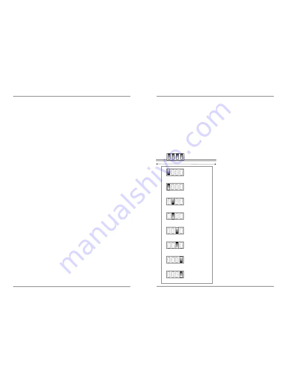
DIP switch settings shown below are set to configure the bridging media
converter for the site installation.
To set network speed(s) and operating mode(s), use a VERY small flatblade
screwdriver or similar device and refer to the table at the left and to the
examples on the next page to set
DIP switch for the site installation.
NOTE: Auto-negotiation is
designed so that a twisted-pair
link will not become operational
until matching capabilities exist in
the devices installed at both ends
of the 802.3u twisted-pair
network.
•When auto-negotiation is
enabled using switch #1, the
bridging media converter
“advertises” rate and mode
capabilities to the network.
Switch #2 and switch #3 are
used selectively to set the
twisted-pair rate and mode to be
“advertised” OR to allow the full
range of rates and modes.
•When auto-negotiation is
disabled using switch #1, the
bridging media converter does
not “advertise” rate and mode
capabilities to the network
Switch #2 and switch #3 are
used to set twisted-pair rate and
mode.
(See examples on next page.)
3
10
Twisted-pair Auto-negotiation ON
Twisted-pair Auto-negotiation OFF
Twisted-pair FULL-DUPLEX
Twisted-pair HALF-DUPLEX
Twisted-pair 100BASE-TX
Twisted-pair 10BASE-T
Fiber FULL-DUPLEX
Fiber HALF-DUPLEX
UP
DOWN
UP
DOWN
UP
DOWN
UP
DOWN
toward network connectors
toward chassis
1 2 3 4


