background image

Management


Trango Broadband Wireless — User Manual M915S Rev C 

Page 

39 


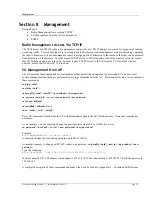
Loading Multiple SUs into the SUDB using DLOAD Command 

To load a full database of SU entries into the AP’s SUDB, you need to create a subscriber database in ASCII text file 
format.  As shown below, each row represents all information for one SU.  Each column is an information field, which 
includes: SU ID, SU to SU group, service level, CIR, MIR, and MAC address. 
 

005 re a B 3000 3000 3000 3000 0000 00 01 de 16 e3 60 


007 re a B 3000 3000 3000 3000 0000 00 01 de 16 e3 7c  
009 re a B 3000 3000 3000 3000 0000 00 01 de 16 e3 7b  
000 

        --- 

End 

of 

file 

indicator 

--- -- - - ---- ---- ---- ---- ---- ----------------- 
 |  |  | |   |   |    |    |    |         |       
 |  |  | |   |   |    |    |    |         | 
 |  |  | |   |   |    |    |    | 

       ------------- MAC Address 

 |  |  | |   |   |    |    |    | 
 |  |  | |   |   |    |    |    | 
 |  |  | |   |   |    |    |     ----------------------- Reserved (should be 0000) 

 |  |  | |   |   |    |    | 
 |  |  | |   |   |    |    | 
 |  |  | |   |   |    |     ---------------------------- MIR Uplink 
 |  |  | |   |   |    | 
 |  |  | |   |   |    | 
 |  |  | |   |   |     --------------------------------- MIR Downlink 
 |  |  | |   |   |  
 |  |  | |   |   | 
 |  |  | |   |    -------------------------------------- CIR Uplink 
 |  |  | |   | 
 |  |  | |   |  
 |  |  | |    ------------------------------------------ CIR Downlink   
 |  |  | | 

 |  |  | | 
 |  |  |   --------------------------------------------- SU2SU Group ID 
 |  |  | 
 |  |  | 
 |  |   ------------------------------------------------ Rate (currently not supported, 
 |  | 


                     value should be a)    

 |  | 
 |   --------------------------------------------------- pr Priority User 
 |   


                 re Regular User 

 | 
 | 
  ------------------------------------------------------ SU ID (1..127)


1. Telnet


into the AP and run the command 

tftpd


on

 to enable TFTP process. 

2.  Tftp the file to the AP from your DOS prompt example: 

tftp <IP of AP> put mySUs.txt

3.  From the AP’s telnet session, run the command 

sudb dload

 to load and activate the SUDB. 

4.  Run the command 

sudb view

 to verify the SUDB entries. 

Run command 

save sudb

 to write the SUDB to non-volatile memory. 

SNMP 

The M915S supports Simple Network Management Protocol (SNMP) for network management.  Network management 
consists of the following 4 categories: configuration, accounting, alarm, and monitoring and control.  These capabilities 
allow the network operator to provide superior services through higher network availability and integrated accounting 
systems.  For more information on SNMP and its uses, you can visit http://www.faqs.org/faqs/snmp-faq/.   
 

Содержание M915S

Страница 1: ...M915S 900 MHz Wireless Broadband System USER MANUAL December 15 2005 Revision A for Firmware Version 2 0 ...

Страница 2: ...P Parameters 12 Configure Basic SU Parameters 14 LED Summary 15 RF Link Loopback Test 16 SU Ranging Test 17 Advanced Setup Page 17 Other Key Parameters 18 Site Survey Page 19 Section 5 Basic Configuration via CLI 20 Access Point Basic Settings 20 Subscriber Unit Database SUDB Settings 23 Subscriber Unit Basic Settings 24 Section 6 Mounting Hardware 27 Cabling and Grounding Considerations 29 Sectio...

Страница 3: ... Bottom of Radio 3 Figure 4 Back of Radio 4 Figure 5 Side of Radio Location of Reverse Polarity SMA Connector 4 Figure 6 Wiring Diagram 5 Figure 7 LED Summary 15 Figure 8 LED and Reset Button Window 15 Figure 9 M915S Mounting Hardware Assembly 27 Figure 10 Alternative Mounting 28 Figure 11 Articulation for M915S with Mono Pod Mount not supplied 29 Figure 12 Grounding of the Radio 29 ...

Страница 4: ... the equipment off and on the user is encouraged to correct the interference by one of more of the following measures 1 Reorient the antenna 2 Increase the separation between the affected equipment and the unit 3 Connect the affected equipment to a power outlet on a different circuit from that which the receiver is connected to 4 Consult the dealer and or experienced radio TV technician for help F...

Страница 5: ...patible with M900S radios such that an M915S AP may be used with M900S SUs and M915S SUs may be used with M900S APs The main difference in the design is a better front back ratio on the internal patch antenna to improve co location at tower sites a redesigned digital section on the printed circuit board and a new package for the M915S SU Network operators can co locate multiple APs at a single cel...

Страница 6: ...ng upstream downstream committed information rate CIR upstream downstream maximum information rate MIR and Priority Setting Each of the above parameters is set in the AP by the system administrator and cannot be controlled at the SU These parameters will be covered in greater detail later in this text When power is first applied to a properly installed SU it will scan all available channels listen...

Страница 7: ...nnels of operation within the 900 MHz ISM band that spans from 902 MHz to 928 MHz The channel width is 6 MHz and the default channel assignments allow for 4 non overlapping channels M915S AP and SU Hardware Components Each radio comes equipped with a power over Ethernet PoE J Box an AC adapter and mounting hardware Radio MU or RU antenna Power Supply 120 VAC 24 VDC J Box Power over Ethernet Inject...

Страница 8: ...tions and Power Connections and powering of the radios is the same for APs and SUs Connect a Cat 5 straight through Ethernet cable we recommend shielded twisted pair between the ODU out door unit port of the J box and the RJ 45 connector on the radio Note that this cable will carry power over Ethernet PoE Trango Broadband Wireless MODEL M915S AP Rev A ACCESS900 TM S N 00000XXXX MAC 00 01 DE 00 02 ...

Страница 9: ...io via the Ethernet port Radio Management Concepts Proper connections to the radios and careful IP routing planning will enable the network administrator to access and manage the radios via TCP IP remotely over the network Radio management over TCP IP can be performed from computers connected to the Ethernet side of each radio Computers connected to the AP can manage the SU over the wireless conne...

Страница 10: ... an M915S radio either through telnet or through the web browser interface the user must know the IP address and password Both APs and SUs feature two levels of passwords Read Write RW and Read Only RO Be sure to change both passwords RW and RO prior to deployment on a live network Passwords can be changed using the password ro and password rw command in either the CLI interface or in the command ...

Страница 11: ...Page 7 Browser Interface Login Page Type the password default trango and continue This will bring up the radio s System Information page Web Browser System Information Page Note System Information page for the SU is similar and is covered in detail later in this text ...

Страница 12: ... wireless link Command Console From this page the user can run any console command that is not interactive i e ipconfig or time sensitive su linktest For a complete list of console commands type help or in the entry field Logout This link will end the current browser session with the radio Help The Browser Interface features useful Help pages that explain all listed parameters To access the Help p...

Страница 13: ...ultcirmir cir dn cir up mir dn mir up sudb delete suid all sudb dload sudb gid suid all 0 15 sudb view survey time 1 10 sec antenna h v e NOTE The majority of the CLI commands will be covered throughout this text as well as in Appendix A Command Set Reference Troubleshooting If you can not telnet into the radio or open a browser session check cable connections ensure proper use of cross over vs st...

Страница 14: ...t be in Opmode ON SU must be in Opmode ON Adequate signal strength must be received at each radio If all of these parameters are met the wireless link will automatically establish itself and Ethernet traffic will begin to pass between the radios Note This section utilizes the Browser Interface as the configuration tool For the equivalent procedure using CLI commands see Section 5 Configuring the A...

Страница 15: ...empt to deliver bandwidth to the AP Maximum setting is 3000 MIR UP Maximum Information Rate from AP to SU Maximum data rate measured in Kbps at which the AP will attempt to deliver bandwidth to this SU Maximum setting is 3000 DEVICE ID MAC address of the SU Creating an SU in the SU Database 1 Connect to the AP see Getting Started and open the Subscriber Database page 2 Enter SU ID range 1 126 3 Se...

Страница 16: ... at a particular cell site The Base ID in the AP must match the Base ID in the SU in order for a link to be established This parameter can only be changed while in Opmode OFF AP ID User definable AP ID 00 FF Default is last two digits of MAC ID One authenticated the AP will automatically assign its AP ID to the SU This parameter can only be changed while opmode is OFF IP Address Subnet Mask Gatewa...

Страница 17: ...ill loose your HTTP session when you Save and Activate Settings 5 Choose Active Channel 1 4 6 Choose Antenna Polarization H or V or choose E for an external antenna Only use E for M915S SU EXT model 7 Ensure default Opmode is ON 8 Save and Activate Settings 9 If this is the first SU to be added to the SUDB reboot the AP After reboot the AP will automatically enter its default Opmode ON after appro...

Страница 18: ...mind if you change the IP Settings of the radio you will loose your HTTP session when you Save and Activate Settings 4 Ensure default Opmode is ON 5 Save and Activate Settings 6 If in Opmode OFF click Activate Opmode At this point if all parameters have been set correctly and the radios are within range a wireless link between the AP and SU will automatically become established Once this occurs th...

Страница 19: ... Only ACT LED RED Ethernet Activity Light 10 100 Link LED GREEN Illuminated when link speed is negotiated at 100 BaseT It is off when link speed is 10 BaseT or not connected RSSI LEDs YELLOW In all modes except Survey the unit s four yellow LEDs indicate the level of RF signal being received from a valid AP Yellow LED 1 rightmost On when RSSI 85 dBm Yellow LED 2 On when RSSI 75 dBm Yellow LED 3 On...

Страница 20: ... user can immediately see which SUs have associated In the page shown SU ID 1 is associated and SU ID 17 is not Consider Power Off status synonymous with not associated RF Link Loopback Test The RF Link Loopback test is one of the built in tools for evaluating the quality of the wireless link Specify an SU ID and time in minutes to conduct the test The test is prioritized so it will take precedenc...

Страница 21: ...6 dBm Lowest setting is 4 dBm This value does not include antenna gain A higher number is more powerful RF RX Threshold Sets the receive threshold of the radio The radio will not process signals received below this level so it is very useful for interference mitigation For a smaller radius of operation use a higher threshold 75 is higher than 80 Target RSSI from SU Used by the powerleveling proces...

Страница 22: ...r uploading firmware MIR Threshold Enable Disable the Maximum Information Rate MIR Threshold The MIR Threshold is the aggregate throughput on the AP at which the AP will start to enforce CIR rules for SUs Active Channel The channel currently being used by the radio RFRX Threshold Sets the receive threshold of the radio The radio will not process signals received below this level so it is very usef...

Страница 23: ... radio must be in Opmode OFF in order to use this feature Enter the number of minutes desired for the survey and select the polarization H V or E for an external antenna Click Start Survey A survey of the default 4 channels will be performed Results are reported in dBm per channel as average and peak A channel is reported to be Clear if the peak and average are below the RF RX Threshold by more th...

Страница 24: ... 56 Opmode on Default Opmode on IP 10 8 0 254 Subnet Mask 255 255 255 0 Gateway 10 8 0 1 Httpd Port 80 Httpd Status listen Telnetd Port 23 Telnetd Status connected 10 8 0 62 1146 Tftpd disabled RF Tx Power 4 dBm RF Rx Threshold 98 dBm MIR Threshold 3 Mbps Ch 01 906 Mhz Ch 02 912 Mhz Ch 03 918 Mhz Ch 04 924 Mhz Default Channel 1 h Active Channel 1 h Broadcast Packet block SU to SU off TCP IP for SU...

Страница 25: ... default to OFF Default Opmode Determines the Opmode ON or OFF of the radio after reboot power cycle When this parameter is set to ON the radio will progress into Opmode ON automatically after a reboot power cycle set defaultopmode on or off Example set defaultopmode on Opmode Start Determines the amount of time the radio will remain in Opmode OFF after reboot power cycle before progressing to the...

Страница 26: ...nal antenna v h e RF RX Threshold Specifies the receiver sensitivity of the AP It is a powerful tool when the radio is in a noisy environment AP will block out any signal received which is below the RF Rx threshold Separate settings exist for both ISM and UNII bands rfrxth 90 85 80 75 70 65 example rfrxth 70 RF TX Power Current transmit power of the AP not including antenna gain power set min max ...

Страница 27: ...y to add one or more SUs to the SUDB There are five basic commands related to the SUDB sudb add sudb cirmir sudb defaultcirmir sudb view and save sudb Adding an SU To add an SU to the database you will need to know the following information 1 MAC ID of the SU printed on the back of the SU 2 Polling priority either PRIORITY or REGULAR Note SUs designated as PRIORITY will get polled more often by th...

Страница 28: ...the command sysinfo sysinfo Hardware Version 0005 FPGA Version 03121104 Checksum 75930BDC Firmware Version SU 1p0a2H0005D04010603 Checksum F4658C90 Device ID 00 01 DE 16 E3 7F S N 01500031 Base ID 1234 AP ID 01 SU ID 1 System Up Time 0 day s 00 37 02 Opmode on Default Opmode on IP 10 8 0 245 Subnet Mask 255 255 255 0 Gateway 10 8 0 1 Httpd Port 80 Httpd Status listen Telnetd Port 23 Telnetd Status...

Страница 29: ...r cycle set defaultopmode on or off Example set defaultopmode on IP Subnet Gateway IP Subnet and Gateway address of radio ipconfig new ip new subnet mask new gateway Example ipconfig 10 1 1 3 255 0 0 0 10 1 1 1 TFTPD TFTPD status on or off TFTPD should be turned on to import a file into the radio such as new firmware Default is off TFTPD will revert to off after reboot power cycle tftpd on off Exa...

Страница 30: ...toscan on or off sw 1 on off default is on TCP IP for AP This software switch 2 when on allows users at the AP side of the network to telnet or HTTP into the SU sw 2 on off default is on Example sw 2 off TCP IP for Local Ethernet Port This software switch 6 when on allows users on the wired side of the SU to telnet or HTTP into the SU regardless of the Opmode sw 6 on off default is on Remarks User...

Страница 31: ... User Manual M915S Rev C Page 27 Section 6 Mounting Hardware 1 2 3 4 5 Not Supplied ITEM NO PART NUMBER QTY 1 Radio 1 2 10 x 3 Threaded Rod 4 3 10 Keps Nut 8 4 V Bracket 2 5 Mono Pod Mount Not Supplied 1 Figure 9 M915S Mounting Hardware Assembly ...

Страница 32: ...ss User Manual M915S Rev C Page 28 ITEM NO PART NUMBER QTY 1 Radio 1 2 10 x 3 Threaded Rod 4 3 10 Keps Nut 8 4 V Bracket 2 5 Mono Pod Mount Not Supplied 1 Alternate Mounting Configuaration 1 2 3 4 5 Not Supplied Figure 10 Alternative Mounting ...

Страница 33: ...Mount not supplied Cabling and Grounding Considerations Grounding Example Figure 12 Grounding of the Radio Proper mounting of the radio includes considerations for grounding Please note that if the radio is attached to a metal pole that is earth grounded no other grounding is necessary If the radio is not earth grounded via the mounting bracket you must attach a grounding wire to the grounding stu...

Страница 34: ... conduit The shield within the Cat 5 cable does not need to be grounded if the radio itself is grounded It is important to consider that most Cat 5 cable will deteriorate over time if exposed to the weather especially direct sunlight Conduit metal or PVC is recommended to protect the cable The radio cable entry point uses NPT pipe threads to allow conduit fittings to be used Important The Ethernet...

Страница 35: ...ative clarity of channels at chosen installation location Site Survey Both the AP and SU provide a powerful on board site survey tool This tool will tell you if there is interference present in the 900 MHz ISM band Command survey time antenna In order to use the survey command the radio must be in Opmode OFF The survey can be performed for up to 10 seconds per channel incrementing by 2 MHz and for...

Страница 36: ...m Once the site survey is completed you are ready to install your radios It is recommended that APs be installed first The reason for this is that the SU has a built in RSSI tool that will help you properly aim the SU at the AP to achieve maximum signal strength AP Search and SU Antenna Alignment Once the AP is installed and aligned in the correct general direction it is time to install the SU The...

Страница 37: ...m will allow you to establish a wireless link but there may not be sufficient fade margin for reliable and continuous operation Example 1 has the wrong freq and antenna settings rssi 1 peak 80 dBm avg 93 dBm 2 peak 80 dBm avg 97 dBm 3 peak 99 dBm avg 99 dBm Example 2 has the correct freq and antenna settings rssi 1 peak 33 dBm avg 74 dBm 2 peak 33 dBm avg 68 dBm 3 peak 33 dBm avg 64 dBm Step 3 If ...

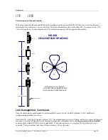
Страница 38: ...tructures 60 60 60 60 CH 3 CH 1 CH 4 CH 2 ADJUSTMENTS IN AZIMUTH WILL NOT HAVE A GREAT EFFECT ON COLOCATION INTERFERENCE M915S COLOCATION SPACING Link Management Commands Once the radios are properly aligned for maximum RSSI ensure the SU s default Opmode is ON and that all configuration parameters are correct Reboot the SU Once the SU enters Opmode ON the authentication process will begin and the...

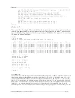
Страница 39: ... 10 RF pings to the designated SU ID The response from each ping will indicate latency in micro seconds and the strength RSSI of the signal received back from the SU for each of the 10 pings Note this command will also tell you the distance from the AP to the SU Example su ping 88 Begin 001 Ping 0 57 dB 374 us 0 0 mi Ping 1 57 dB 373 us 0 0 mi Ping 2 57 dB 373 us 0 0 mi Ping 3 56 dB 373 us 0 0 mi ...

Страница 40: ...RxErr 0 SU Tx 100 SU Rx 100 SU RxErr 0 866 ms 2956 kbps 5 AP Tx 100 AP Rx 100 AP RxErr 0 SU Tx 100 SU Rx 100 SU RxErr 0 866 ms 2956 kbps 6 AP Tx 100 AP Rx 100 AP RxErr 0 SU Tx 100 SU Rx 100 SU RxErr 0 866 ms 2956 kbps 7 AP Tx 100 AP Rx 100 AP RxErr 0 SU Tx 100 SU Rx 100 SU RxErr 0 866 ms 2956 kbps 8 AP Tx 100 AP Rx 100 AP RxErr 0 SU Tx 100 SU Rx 100 SU RxErr 0 866 ms 2956 kbps 9 AP Tx 100 AP Rx 10...

Страница 41: ...ovides the ability to correct for missing or corrupted packets of data by asking the sender to re transmit the data Both the AP and SU units implement a form of ARQ known as ARQ with Selected Repeat The units makes a first attempt at transmitting a data frame using the 3 250 Mbps rate Then if a re try is required the 2nd attempt will also be at 3 250 Mbps The 3rd and 4th attempts will be at a rate...

Страница 42: ...t the management of associated SUs In fact most system management functions are performed by issuing commands from the AP Presented below are a few examples of these commands su ping suid su status suid su ipconfig suid new IP new subnet new gateway su password suid all rw ro new password new password su reboot all suid su testrflink all suid r su sw suid sw on off Note SU commands issued from the...

Страница 43: ... Group ID Rate currently not supported value should be a pr Priority User re Regular User SU ID 1 127 1 Telnet into the AP and run the command tftpd on to enable TFTP process 2 Tftp the file to the AP from your DOS prompt example tftp IP of AP put mySUs txt 3 From the AP s telnet session run the command sudb dload to load and activate the SUDB 4 Run the command sudb view to verify the SUDB entries...

Страница 44: ...f octets of payload transmitted from the AP s RF port suRFOutOctets Number of octets of payload received on the AP s RF port AP Bandwidth Monitoring aptrafficEthRXAvgThroughputLog Average payload data throughput in Kbits sec received on the Ethernet port over the period of 1 minute aptrafficEthTXAvgThroughputLog Average payload data throughput in Kbits sec transmitted from the Ethernet port over a...

Страница 45: ...3 Copy trango_M915Sap_1p0 mib file to C Program Files SNMPc Network Manager mibfiles 4 Copy autoico txt file to C Program Files SNMPc Network Manager mibfiles 5 Copy trango ico file to C Program Files SNMPc Network Manager bitmaps 6 The MIB needs to be compiled into the SNMPc database By default the Read Community is set to public and Write Community is set to private in the AP The Trap Community ...

Страница 46: ...U Display complete list of commands and syntax ro rw help command AP SU Display specific command syntax ro rw ipconfig new ip new subnet mask new gateway AP SU Assign radio s IP subnet mask and gateway IP rw linktest txrx rxtx pkt len bytes of pkts of cycle AP SU Loopback test to check quality of the wireless link Variable parameters include pktlen 64 1760 0 pkts 1 500 of cycles 1 100000 ro rw log...

Страница 47: ...aseid base id 4 oct AP SU Set base station id Base ID XXXX where X any alphanumeric character except rw set defaultopmode on off AP SU Set default Opmode to ON or OFF Factory set default Opmode is OFF rw set httpport port AP SU Set or display HTTPD port number port 1 65534 default port 80 rw set snmpcomm read write trap id trap all AP SU Set SNMP read or write or trap community string rw set telne...

Страница 48: ...rw survey search time sec antenna h v e AP SU Spectrum analysis of the entire band and near band search time 1 10 sec per channel Opmode OFF only ro rw Sw AP SU Display current sw setting ro rw sw 0 on off AP SU set sw 0 enable or disable packet filter for broadcast multicast packets on filtering default on rw sw 1 on off SU Enable or disable SU s autoscan AP feature If on SU will automatically sc...

Страница 49: ...pdateflash systemsetting ss AP SU Save current settings This command can be issued in several ways save ss updateflash systemsetting save systemsetting and updateflash ss rw updateflash mainimage fpgaimage current chscksum new checksum AP SU Retrieve uploaded firmware from TFTP buffer verify checksum and write to flash memory at main or FPGA image section rw updateflash sudb AP Save SUDB into flas...

Страница 50: ...6 5 MHz null to null 40 dB down 2nd Harmonic atten Per CFR47 part 15 407 LO Supression Per CFR47 part 15 407 Receiver Specifications Storable Channels 4 memory locations Agility 906 to 924 MHz in 1 MHz increments Default channels Channel 1 906 MHz Channel 2 912 MHz Channel 3 918 MHz Channel 4 924 MHz Cascade Noise Figure 7 dB Receiver Sensitivity 3 250 MBPS Rate 90 dBm typical 1600 byte packet 1x1...

Страница 51: ... cause damage to unit Mechanical and Environmental Specifications General Material High Temp Polycarbonate radome and diecast metal enclosure AP_ High temp ABS enclsure SU Size 12 5 x 8 x 2 75 including mounting studs Weight 4 lb Mounting 2 U Brackets all thread rod nuts and washers AP Articulating pole mount SU Connectors Indicators RF Output Integral internal patch antenna per Part 15C 15 203 Ex...

Страница 52: ...ins 1 2 3 6 Indicators 2 LEDs to indicate power and a connection to radio Protection Resettable fuse for DC input Integrated Antenna M915S SU and M915S SU EXT Type Dielectric loaded Patch Antenna Polarization Vertical or Horizontal Polarization electrically selectable Frequency 902 to 928 MHz Gain 9 dBiL 1 dB Az Beamwidth 60º 3 dB pts El Beamwidth 60º 3 dB pts Cross Pol 15 dB Front Back Ratio 15 d...

Отзывы: