50
CLCH-IM-16A
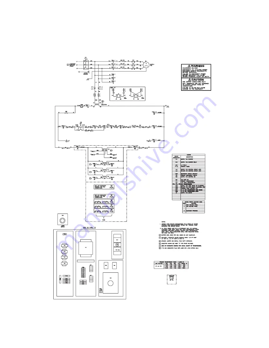
Figure 44Typical High Voltage Wiring Schematic
Страница 1: ...e done by qualified experienced technicians Installation CLCH IM 16A and Maintenance Manual Library Service Literature Product Section Air Handling Product Central Station Air Handlers Model T Series Climate Changer Literature Type Installation Maintenance Sequence 2 Date March 1999 File No CLCH IM 16A 3 99 T Series Climate Changer Central Station Air Handlers Draw Thru and Blow Thru Unit Sizes 3 ...
Страница 2: ...AILABLE REFRIGERANT USED IN ANY TYPE OF AIR CONDITIONING OR REFRIGERATING EQUIPMENT SHOULD BE RECOVERED FOR REUSE RECOVERED AND OR RECYCLED FOR REUSE REPROCESSED RECLAIMED OR PROPERLY DESTROYED WHENEVER IT IS REMOVED FROM EQUIPMENT NEVER RELEASE TO THE ATMOSPHERE Warning and Cautions Notice that WARNING and CAUTION appear at appropriate intervals throughout this manual WARNING WARNING indicates a ...
Страница 3: ...6 General 16 Unit Assembly All Sizes 16 Component Installation Requirements 22 Fan Section 22 Set Up 25 Duct Connections 28 Drain Pan 30 Coil Piping And Connections 32 Refrigerant Coil Piping 46 General Refrigerant Piping Recommendations 47 Wiring 49 Installation Checklist 51 Prestart Up Checks 51 Start Up 53 Start Up Procedures 53 Periodic Maintenance 59 Drain Pans 60 Air Filters 60 Fans 61 Fan B...
Страница 4: ...ntrollers and end devices Trane T Series Climate Changers ship as complete assemblies or sectional subassemblies Some assembly is required when the units ship as subassemblies Operating Environment The T Series Climate Changer TSC is an outdoor air handler When considering the placement of the TSC it is important to consider the operating environment The acceptable ambient temperature range for un...
Страница 5: ... A BRIEF OVERVIEW OF THE OPTIONAL FACTORY MOUNTED CONTROLS FOR MORE IN DEPTH UNDERSTANDING OF THE PROGRAMMABLE CONTROL MODULE PCM REFERENCE INSTALLATION GUIDE EMTX IN 11A APPLICATION GUIDE EMTX AG 1 OPERATORS GUIDE EMTX OG 4 INSTALLATION OPERATION AND PROGRAMMING GUIDE CLCH IOP 1 AND INSTALLATION OPERATION AND MAINTENANCE MISC IOM 5 Most control components are mounted inside the units Depending on...
Страница 6: ...e following instructions should be completed 1 Make specific notation describing the damage on the freight bill 2 Report all claims of shipping damage to the delivering carrier immediately 3 Keep damaged material in the same location as it was received It is the receiver s responsibility to provide reasonable evidence that the concealed damage was not incurred after delivery 4 Notify the Trane sal...
Страница 7: ... 40 50 Filter Mixing 225 232 270 367 393 443 490 526 624 687 933 1025 1148 Economizer 314 377 419 582 637 677 740 827 902 1118 1291 1544 1785 Exhaust 88 105 115 134 145 154 167 187 201 219 265 283 399 Air Blender 191 242 279 355 380 399 431 477 562 614 822 888 1080 Flat Filter 71 84 91 109 122 130 140 157 164 177 235 249 365 Angled Filter 154 199 232 242 261 290 312 338 355 389 545 590 684 Bag Fil...
Страница 8: ...ed Blank Access 307 319 350 M L Blank Access 472 491 538 Large Blank Access 775 870 1056 Small Coil Weight includes 2 row UW 933 1040 1237 Med Coil Weight includes 8 row UW 1850 2143 2608 M L Coil Weight includes 10 row W 3372 3884 4738 Large Coil Weight includes 10 row W N A N A N A Moisture Eliminator 710 786 928 Internal Face Bypass 753 852 1002 Face Damper 753 852 1002 Front Horiz Disch Fan We...
Страница 9: ... 79 107 119 215 260 286 334 372 406 591 765 989 Energy Efficient TEFC 45 75 96 140 160 233 289 332 384 471 536 764 820 1302 VAV ODP 42 87 91 132 147 230 220 331 352 450 509 796 825 1000 Table 5 Approximate Dry Cooling Coil Weights Type UU UF and UW Fin Series 168 Weights in lb Unit Size Rows 3 6 8 10 12 14 17 21 25 30 35 40 50 66 80 100 2 41 58 69 88 110 122 138 175 197 222 247 274 358 458 548 666...
Страница 10: ... Series 168 Weights in lb Coil Type Rows W K P2 P4 P8 D DD WD WA WC TT NS 1 53 53 48 73 2 81 93 56 59 81 54 4 119 155 95 96 111 135 127 6 157 217 136 142 189 198 164 8 194 285 175 185 243 236 201 10 232 341 297 307 238 12 270 403 351 345 275 Table 8 Unit Size 8 Approximate Dry Coil Weights Fin Series 168 Weights in lb Coil Type Rows W K P2 P4 P8 D DD WD WA WC TT NS 1 71 71 66 97 2 108 124 75 77 10...
Страница 11: ...eights Fin Series 168 Weights in lb Coil Type Rows W K P2 P4 P8 D DD WD WA WC TT NS 1 103 103 103 142 2 165 185 119 122 166 116 4 257 316 211 213 228 284 274 6 349 448 306 313 402 421 361 8 441 579 400 410 521 513 452 10 533 710 638 661 542 12 625 842 756 75 633 Table 11 Unit Size 14 Approximate Dry Coil Weights Fin Series 168 Weights in lb Coil Type Rows W K P2 P4 P8 D DD WD WA WC TT NS 1 107 107...
Страница 12: ...mate Dry Coil Weights Fin Series 168 Weights in lb Coil Type Rows W K P2 P4 P8 D DD WD WA WC TT NS 1 148 149 139 214 2 241 264 191 197 241 184 4 379 451 330 333 364 411 396 6 517 637 475 489 581 600 528 8 655 835 617 636 752 738 664 10 793 1009 922 943 800 12 931 1195 1092 1081 936 Table 14 Unit Size 25 Approximate Dry Coil Weights Fin Series 168 Weights in lb Coil Type Rows W K P2 P4 P8 D DD WD W...
Страница 13: ...837 647 661 771 794 709 8 889 1091 842 862 1001 897 899 10 1082 1333 1230 1257 1088 12 1275 1582 1459 1450 1278 Table 16 Unit Size 35 Approximate Dry Coil Weights Fin Series 168 Weights in lb Coil Type Rows W K P2 P4 P8 D DD WD WA WC TT NS 1 275 N A N A N A 212 224 333 2 379 413 340 298 4 616 717 660 642 6 853 1022 943 974 879 8 1091 1333 1224 1211 1116 10 1328 1631 1505 1544 1353 12 1565 1936 178...
Страница 14: ...97 2061 12 2397 2853 2672 2666 2431 Table 19 Unit Size 66 Approximate Dry Coil Weights Fin Series 168 Weights in lb Coil Type Rows W K P2 P4 P8 D DD WD WA WC N NS 1 521 N A N A N A 387 441 660 648 2 738 789 4 1242 1383 1302 1275 660 6 1740 1980 1866 1908 1776 8 2241 2577 2430 2409 2277 10 2742 3171 2994 3042 2778 12 3243 3768 3555 3543 3279 Table 20 Unit Size 80 Approximate Dry Coil Weights Fin Se...
Страница 15: ...ions or raise units above personnel Failure to follow all instructions may result in personal injury or equipment damage 1 Before lifting the unit estimate the approximate center of gravity and test lift the unit to determine balance and stability NOTE PREPARATION OF THE ROOF CURB OR PIER MOUNT AND ROOF OPENINGS SHOULD BE COMPLETED BEFORE LIFTING UNIT TO THE ROOF SEE THE ASSEMBLY SECTION OF THIS M...
Страница 16: ...l Lifting section of this manual to include test lifting Lift the hood sections individually as shown in Figure 2 Attach the cables chains or straps to lifting lugs as shown Attach the hood to the unit only after all sections are in place Figure 2 Inlet and Exhaust Hood Lifting Lifting the External Pipe Cabinet Chase CAUTION Do not attach the pipe chase to the unit prior to lifting the unit Doing ...
Страница 17: ...16A Figure 4 Field Unit Lifting Figure 5 Shipping Block Removal Rigging and spreader bars not furnished by Trane Recommended attachment to lifting lugs Remove ALL wooden blocks before installing unit to roof curb ...
Страница 18: ...ensate flow 4 Allow the proper height for condensate drain requirements Insufficient height may inhibit condensate drainage and result in flooding the unit 5 Provide adequate lighting for maintenance personnel to perform maintenance duties 6 Provide permanent power outlets in close proximity of the unit for installation and maintenance Coil Filter Fan Drive A B C D Table 22 Service Clearances in i...
Страница 19: ...le to support the entire weight of the unit roof curb and accessories See Table 1 thru Table 4 for unit and accessory weights q Prepare the roof curb or pier mount and roof openings before hoisting the unit to the roof q Check that the gasketing is intact and provides an airtight seal with the unit base Refer to the applicable roof curb installation manual q Complete all ductwork piping and electr...
Страница 20: ...TOLERANCE IN BOTH HORIZONTAL AXES FAILURE TO LEVEL THE UNIT PROPERLY CAN RESULT IN CONDENSATE MANAGEMENT PROBLEMS SUCH AS STANDING WATER INSIDE THE UNIT STANDING WATER AND WET SURFACES INSIDE AIR HANDLING UNITS CAN RESULT IN MICROBIAL GROWTH MOLD IN THE DRAIN PAN THAT MAY CAUSE UNPLEASANT ODORS AND SERIOUS HEALTH RELATED INDOOR AIR QUALITY PROBLEMS For vertical discharge units allow space under th...
Страница 21: ...0 16 x 3 4 self drilling screws Figure 10 Roof Assembly Joints Control Wiring Assembly at Section Splits All Unit Sizes Reference Figure 11 1 Sections Must be together 2 Remove outer and inner raceway access covers on both sections adjacent to shipping split 3 Remove top foam blocks in raceway 4 Route wire harness es under inner roof through raceway and make connection to corresponding wire harnes...
Страница 22: ... in Figure 12 5 Crimp down the two overhanging ends and secure with 10 16 x 3 4 sheet metal screws Figure 12 Roof Assembly at Section Splits Base Assembly 1 Slide the 1 2 threaded rod through the hole in each of the two joined base sections as shown 2 Install two flat washers lockwasher and 1 2 nut at each rod end Tighten both nuts 3 Install the flashing piece on the base assembly Secure in place ...
Страница 23: ...NOTE THE HOOD ASSEMBLY SHOULD BE SUPPORTED BY CHAINS SPREADER BAR OR OTHER MEANS SEE LIFTING INSTRUCTIONS SECTION WHEN INSTALLED TO THE UNIT MOUNTING TAPE AND HARDWARE ARE LOCATED INSIDE THE UNIT 1 Apply the 1 butyl tape in a strip around the perimeter of the hood 2 Using the lifting lugs hoist the hood and center it over the panel opening as shown in 3 Attach the hood to the unit with the 1 4 20 ...
Страница 24: ... side panel with 10 self drilling screws Figure 16 4 Attach the Z bar to the gutter with 10 screws NOTE USE ALL HOLES DRILLED IN THE ATTACHMENT FLANGES 5 Attach the pipe cabinet side attachment flanges to the unit panel with 10 screws 6 If piping is already run through the roof follow steps 6 through 13 First remove the Z bar from the pipe cabinet 7 Remove the paper backing from the butyl tape on ...
Страница 25: ... power before opening door Failure to disconnect power before servicing can cause severe personal injury 1 Disconnect the power to the unit 2 Open the filter section access door 3 Remove the adjustable block off from the filter track 4 Slide the filters into the tracks Note that bag filters must be installed with the pleats in the vertical plane 5 Slide the adjustable block offs into the filter tr...
Страница 26: ...unit ships with the internal isolation base secured to prevent damage to the fan and motor assembly during shipment To activate the isolation remove the shipping tie downs Shipping Tie down Removal There are four types of shipping tie downs used to secure the isolation base q Sizes 3 8 use a 3 8 x1 pipe See Figure 18 q Sizes 10 30 except plug fans use washers with a bolt See Figure 18 q Sizes 35 5...
Страница 27: ...djust the isolators to achieve the proper operation height of the fan and motor isolation base The isolators are bolted between the fan and motor isolation base There are five designs based on unit size and fan type Specific isolator clearances are listed in Table 23 The measurement is taken between the top of the floor panel or support channel on sizes 66 100 and the bottom of the isolation base ...
Страница 28: ...D FACE AND BYPASS DAMPERS ARE DESIGNED FOR THE DAMPER ACTUATORS TO BE DIRECT COUPLED AND INSTALLED IN THE AIR STREAM IF OTHER PROVISIONS ARE REQUIRED MODIFICATIONS TO THE SECTION WILL BE THE RESPONSIBILITY OF THE INSTALLING CONTRACTOR Rods Operators and Settings The T Series Climate Changer is available with factory mounted controls or end devices If the unit is not ordered with controls or end de...
Страница 29: ... 31 9 11 4 13BI 38 0 N A 40 0 N A 15 FC 14 1 5 0 31 9 11 4 12 16 FC 18 0 6 4 40 5 14 4 15 BI 38 0 N A 40 0 N A 16 FC 18 0 6 4 40 5 14 4 14 18 FC 23 1 8 3 52 2 18 6 16 BI 44 0 N A 50 0 N A 18 FC 23 1 8 3 52 2 18 6 17 20 FC 24 0 9 0 54 0 19 5 18 BI 54 0 N A 60 0 N A 20 FC 24 0 9 5 54 0 19 5 21 22 FC 25 0 9 5 56 0 21 0 20 BI 66 0 N A 74 0 N A 22 FC 25 0 9 5 56 0 21 0 25 30 25 FC 26 5 10 0 59 7 22 5 2...
Страница 30: ...nsducer once every minute Input Power Signal The only input signal the VCM needs is the 24 VAC power connected to terminals TB5 and TB6 Output Velocity Signal The 2 10 VDC linear output signal from the VCM represents air velocity This voltage can be converted to represent cfm or L s using the formula and Table 26 following For example if the VCM on a Size 21 T Series Climate Changer has a 10 volt ...
Страница 31: ...limate Changer should be installed in accordance with the standards of the National Fire Protection Association NFPA for installing of air conditioning and ventilating systems other than residence type NFPA 90A and residence type warm air heating and air conditioning systems NFPA 90B See unit submittal documentation for additional duct mounting information To ensure the highest fan efficiency duct...
Страница 32: ...performance Damper Sections Standard damper sections include mixing sections filter mixing sections face damper sections internal face and bypass sections and economizer sections Duct work attached to the standard damper sections should be sized to fit the opening of the damper This information is provided in the submittals When using lined duct ensure that the insulation does not obstruct the dam...
Страница 33: ...age to the equipment and or building Threaded condensate drain connections are provided on only one side of the coil section Pitch the connection lines horizontal or downward toward an open drain Trane recommends installing a plug to facilitate cleaning of the trap IMPORTANT PROPER TRAPPING OF THE COOLING COIL CONDENSATE DRAIN LINES IS NECESSARY FOR PROPER CONDENSATE MANAGEMENT IMPROPER TRAPPING C...
Страница 34: ...epth for the condensate trap Positive Pressure Section The positive pressure section requires a different design than the negative pressure trap Refer to Figure 27 and the formula provided to determine the minimum trap depth 3C Normal Operation L H J H 1 for each 1 of maximum negative static pressure 1 J half of H L H J Pipe Diameter Insulation H 1 for each 1 of maximum negative pressure 1 J 1 2 H...
Страница 35: ... contractor should supply the pipe nipples couplings etc for installation NOTE WHEN USING ELECTRONIC VALVE ACTUATORS ON CHILLED WATER VALVES THE VALVE SHOULD BE MOUNTED ABOVE THE HORIZONTAL POSITION TO PREVENT COLLECTION OF CONDENSATE IN THE ACTUATOR ELECTRONIC CIRCUITS AND SUBSEQUENT ACTUATOR FAILURE WHEN USING ELECTRONIC VALVE ACTUATORS ON HOT WATER OR STEAM COILS THE ACTUATOR SHOULD BE INSTALLE...
Страница 36: ...tr 7 8 1 3 8 7 8 1 3 8 3 16 4 5 8 1 3 8 5 8 1 3 8 6 23 4 6 8 1 4 18 Full 1 1 8 1 5 8 3 16 18 1 1 8 1 5 8 4 6 1 4 9 Half 1 1 8 1 5 8 7 8 1 3 8 3 16 9 1 1 8 1 5 8 Note 1 1 3 8 4 1 4 4 Qtr 7 8 1 3 8 7 8 1 3 8 3 16 4 5 8 1 3 8 5 8 1 3 8 8 10 27 4 6 8 1 4 21 Full Note 2 1 5 8 3 16 21 1 1 8 1 5 8 4 6 1 4 10 Half 1 1 8 1 5 8 7 8 1 3 8 3 16 10 1 1 8 1 5 8 7 8 1 3 8 4 1 4 5 Qtr 7 8 1 3 8 7 8 1 3 8 3 16 5 7...
Страница 37: ...tion Liquid Suction Table 29 UF Refrigerant Coil Connections Inches Unit Size Header Height Rows Dist Tube No Circuits Circuiting 2 Distributors 4 Distributors 8 Distributors Liquid Suction Liquid Suction Liquid Suction 35 40 57 4 6 8 1 4 45 Full 1 3 8 1 5 8 3 16 45 1 1 8 1 5 8 4 6 1 4 22 Half 1 3 8 1 5 8 Note 1 1 3 8 3 16 22 1 1 8 1 5 8 7 8 1 3 8 50 2 32 4 6 8 1 4 50 Full 1 3 8 1 5 8 3 16 50 1 1 ...
Страница 38: ...G R 3 11 10 9 16 13 11 16 4 1 2 6 1 2 21 5 8 2 5 8 1 1 2 6 11 12 1 16 14 3 16 4 1 2 6 1 2 24 5 8 2 5 8 1 1 2 8 11 13 15 16 17 1 16 4 1 2 6 1 2 26 3 8 2 5 8 1 1 2 10 11 13 15 16 17 1 16 4 1 2 6 1 2 26 3 8 2 5 8 1 1 2 12 11 16 7 16 19 9 16 4 1 4 6 3 4 33 3 8 2 5 8 2 14 11 13 15 16 20 13 16 4 1 4 6 3 4 25 7 8 2 5 8 2 17 11 18 15 16 22 1 16 4 1 4 6 3 4 38 3 8 2 5 8 2 21 11 20 5 8 25 3 4 3 3 4 7 42 1 8...
Страница 39: ...52 7 8 55 3 4 69 1 2 2 66 27 3 4 30 7 8 5 1 2 7 25 32 11 1 2 47 1 8 50 1 2 66 3 4 69 7 8 96 1 8 2 80 31 1 2 34 5 8 5 1 2 8 1 16 11 1 2 54 5 8 58 78 81 1 8 101 1 8 2 1 2 100 34 5 8 37 3 4 5 1 2 8 1 16 11 1 2 60 7 8 64 1 4 87 3 8 90 1 2 113 5 8 2 1 2 AIR FLOW AIR FLOW A B C D E F G J K M 1 7 R NPT EXT Supply R H R NPT EXT Return L H R NPT EXT Return R H R NPT EXT Supply L H 3 8 NPT Ext Vent 3 8 NPT ...
Страница 40: ...2 6 1 2 26 3 8 2 5 8 1 1 2 12 11 16 7 16 19 9 16 4 1 4 6 3 4 33 3 8 2 5 8 2 14 11 13 15 16 20 13 16 4 1 4 6 3 4 25 7 8 2 5 8 2 17 11 18 15 16 22 1 16 4 1 4 6 3 4 38 3 8 2 5 8 2 21 11 20 5 8 25 3 4 3 3 4 7 42 1 8 2 5 8 2 1 2 25 11 25 3 4 26 7 8 3 3 4 7 45 1 4 2 5 8 2 1 2 30 11 25 3 4 26 7 8 3 3 4 7 45 1 4 2 5 8 2 1 2 35 11 1 2 29 7 16 30 9 16 4 3 8 7 1 8 58 3 4 3 5 32 2 1 2 40 11 1 2 29 7 16 30 9 1...
Страница 41: ...1 9 16 2 1 2 25 15 1 2 25 3 4 28 7 8 3 15 16 7 3 16 9 5 16 11 9 16 2 1 2 30 15 1 2 25 3 4 28 7 8 3 15 16 7 3 16 9 5 16 11 9 16 2 1 2 35 16 32 9 16 29 7 16 4 3 16 7 7 16 9 5 8 11 13 16 2 1 2 40 16 32 9 16 29 7 16 4 3 16 7 7 16 9 5 8 11 13 16 2 1 2 Table 34 UU 4 and 8 Row RH and LH Medium Coil Connection Dimensions in inches UU Coil Section D Unit Size C 4 ROW 8 ROW R E F 3 N A N A N A N A 2 5 8 21 ...
Страница 42: ...ize A B E F G J K M R 50 18 3 4 21 7 8 60 35 5 8 39 52 3 4 55 7 8 69 5 8 2 66 27 3 4 30 7 8 11 1 2 47 1 8 50 1 2 66 3 4 69 7 8 74 1 8 2 80 31 1 2 34 5 8 11 1 2 54 5 8 58 42 81 1 8 101 1 8 2 1 2 100 34 11 16 37 3 4 11 1 2 60 11 16 64 1 4 87 3 8 90 7 16 113 5 8 2 1 2 Table 36 Coil Type UU 4 and 8 Row UW 4 6 and 8 Row RH and LH Medium Coil Drain and Vent Location Dimensions in inches UW COIL SECTION ...
Страница 43: ...ain and Vent Locations AIR FLOW 10 1 2 12 24 1 8 25 1 2 4 2 1 1 4 NPT INT Return 1 1 4 NPT INT Supply Sq Hd Pipe Plug 1 2 NPT Drain 1 2 NPT Vent 1 2 NPT Vent 1 2 NPT Drain Water Inlet Water Outlet Water Outlet Water Inlet A 6 6 AIR FLOW 2 4 Row 6 Row Table 37 Coil Type P2 18 24 Headers Dimensions in Header A 18 16 5 24 22 5 ...
Страница 44: ...W 2 Row 4 Row 1 68 0 18 B A B A Table 38 Coil Type P4 18 24 Headers Dimensions 2 Row in inches Header A B 18 10 5 6 24 13 5 9 Table 39 Coil Type P4 18 24 Headers Dimensions 4 Row in inches Header A B 18 7 5 9 24 10 5 12 1 2 NPT Vent 1 2 NPT Vent 1 2 NPT Drain Water Inlet Water Outlet Water Outlet Water Inlet 3 AIR FLOW 6 Row 8 Row A 7 1 2 A 4 1 2 1 2 NPT Drain Table 40 Coil Type P4 18 24 Headers w...
Страница 45: ... Row A A B C D Table 41 Coil Type P8 18 24 Headers 4 Row Dimensions in inches Header A B C D 18 7 5 9 1 2 1 2 24 10 5 12 0 4 5 30 13 5 15 1 2 1 2 Table 42 Coil Type P8 18 24 Headers 8 Row Dimensions in inches Header A 18 16 5 24 22 5 30 28 5 G A B C D E F H G A B C D E F H 2 1 2 NPT INT Return 1 2 NPT INT Vent 1 2 NPT INT Drain 2 1 2 NPT INT Supply 2 1 2 NPT INT Return 1 2 NPT INT Vent 1 2 NPT INT...
Страница 46: ...AUTION Failure to properly protect coils not in use during freezing temper atures may result in coil freeze up damage Refer to the section titled Coil Winterization for specific instructions Steam Coil Piping Figure 38 Typical Piping for Type NS Steam Coils and Horizontal Tubes for Horizontal Airflow Table 43 Coil Type W with 18 24 30 and 33 Headers and with Drain and Vent Locations Dimensions in ...
Страница 47: ...trap selection and installation is necessary for satisfactory coil performance and service life For installation use the following steps 1 Install the steam trap discharge 12 inches below the condensate return connection 12 inches provides sufficient hydrostatic head pressure to overcome trap losses and ensures complete condensate removal Use float and thermostatic traps with atmospheric pressure ...
Страница 48: ...for fin damage and straighten if necessary q Check that the coil is installed correctly with the air flow in the same direction as indicated on the nameplate or coil casing Code of System Components Piping Diagrams FT Float and thermostatic steam trap BT Bucket steam trap GV Gate valve OV Automatic two position on off control valve TV Automatic three way control valve VB Vacuum breaker CV Check va...
Страница 49: ...r velocity is below these minimums vent by following one of the followings methods q Install an air vent in the top pipe plug tapping of the return header q Vent from the top return header horizontally to the return piping when the return line rises and is above the top of the coil Refrigerant Coil Piping Units that are UL listed shall not have refrigerant temperatures and pressures exceeding that...
Страница 50: ... glass between the expansion valve and filter drier The moisture indicator sight glass must be sized to match the size of the liquid line at the thermal expansion valve 2 Size liquid line shutoff valve with an access port using the selected liquid line OD and install it close to the condenser 3 Minimize use of other valves tube bends and reducers since these items tend to increase pressure drop an...
Страница 51: ...rmanently Liquid Line Sizing All compressors have a Refrigerant Charge Limit RCL that must not be exceeded Since the RCL and pressure drop are in direct conflict with each other Trane recommends that the liquid line be sized as small as possible while maintaining a low enough pressure drop to ensure 5 F of subcooling at the expansion valve Suction Line Sizing Suction line tubes must be sized to ma...
Страница 52: ... and resultant equip ment damage Fan motors require motor overload protective devices that are rated or selected in compliance with the National Electric Code or Canadian Electric Code Specific unit and motor connection diagrams are provided on the unit If wiring directly to the motor a flexible connection at the motor to permit fan belt adjustment should be provided Fractional horsepower motors m...
Страница 53: ...50 CLCH IM 16A Figure 44 Typical High Voltage Wiring Schematic ...
Страница 54: ...ails on the installation of units with factory mounted controls 13 Complete electrical connections to the unit and PCM 14 Leave the unit installation and maintenance manual with the unit Prestart Up Checks Before operating the unit complete the following checks for safe and efficient operation WARNING Disconnect electrical power source when connecting or dis connecting electrical wires for test pr...
Страница 55: ...check operation Drain lines should be open q If unit has a refrigerant coil it must be charged leak tested and ready for operation according to instructions provided with the condenser equipment Adjust superheat setting q Check that air filters are in place and positioned properly q Remove all foreign material from the drain pan and check pan opening and condensate line for obstructions q Check un...
Страница 56: ...in pan opening and condensate line for obstructions 7 Check unit for debris 8 Reference CLCH IOP 1 for more details on the start up of units with factory mounted controls Start Up Procedures After completing all prestart up checks and procedures the unit may be started The following checks and adjustments should be made during initial start up WARNING Disconnect electrical power prior to access in...
Страница 57: ... Fan rpm can be determined by using a strobe type tachometer or revolution counter Sheave Alignment Align the fan and motor sheaves by using a straightedge The straightedge must be long enough to span the distance between the outside edges of the sheaves When the sheaves are aligned the straightedge will touch both sheaves at points A through D to confirm that the shaft is parallel For uneven widt...
Страница 58: ...e 46 Typical Drive Belt Label WARNING Disconnect electrical power source and allow all rotating equipment to stop completely before inspecting or servicing the unit Failure to do so may result in personal injury or death from elec trical shock or moving parts Disconnect electrical power prior to access into a fan or ductwork Even when locked out electrically fans may cause injury or damage if the ...
Страница 59: ...power requirement Use Table 47 to find the proper belt tension and refer to the inset for an example To use the table you must know q Fan design brake horsepower bhp per belt not motor hp q Fan rpm q Fan sheave pitch diameter found by measuring where the middle of the belt rides in the sheave See Figure 47 q Type of belt cross section stamped on the belt ...
Страница 60: ...Installation and Maintenance 57 Table 47 Belt Tension ...
Страница 61: ...or sheave pitch diameter 5 7 inches eight groove Fan sheave pitch diameter 10 0 inches eight groove Fan horsepower 2 4 bhp Fan rpm 1000 rpm Belt type C Sheave span 32 inches Belt speed 10 12 X 3 14 X 1000 2618 T 24 750 X 24 bhp 2 belts 2618 113 4 lb F 13 4 40 16 9 6 lb Also D Belt span inches 64 32 64 50 in Therefore the belt tensiometer should read 11 5 pounds force at 15 16 inch deflection This ...
Страница 62: ...onditions include high speeds moist or dirty air or high temperatures q Relubricate motor bearings in accordance with motor manufacturer s recommendations if operating conditions include high speeds moist or dirty air or high temperatures q Check and adjust fan belt tension Every Three to Six Months q Check fan bearing grease line connections Lines should be tight to the bearings q Relubricate fan...
Страница 63: ...izer manufacturer s instructions regarding the use of the product 12 Immediately rinse the drain pan thoroughly with fresh water to prevent potential corrosion from the cleaning solution of the drain pan and drain line components 13 Allow the unit to dry thoroughly before putting the system back into service 14 Determine and correct the cause of the microbial contamination 15 Be careful that the c...
Страница 64: ...es of fans should be cleaned immediately The suggested procedure for cleaning these surfaces is 1 Disconnect all electrical power to the unit 2 Don the appropriate personal protective equipment PPE 3 Use a portable vacuum with HEPA filtration to remove the loose dirt and organic matter The filter should be 99 97 efficient at 0 3 micron particle size 4 If no microbial growth mold exists thoroughly ...
Страница 65: ...o do so may result in personal injury or death from elec trical shock or entanglement in moving parts Disconnect electrical power prior to access into a fan or ductwork Even when locked out electrically fans may cause injury or damage if the impeller is subject to wind milling The impeller should be Set Screws 2 Set Screws 2 Table 49 Recommendations for Grease Lubricated Fan Bearings Greasing Inte...
Страница 66: ...leaning is dependent on the operating hours of the system filter maintenance and efficiency and dirt load IMPORTANT COILS BECOME EXTERNALLY FOULED AS A RESULT OF NORMAL OPERATION DIRT ON THE SURFACE OF THE COIL REDUCES IT S ABILITY TO TRANSFER HEAT THAT CAN RESULT IN COMFORT PROBLEMS INCREASED RESISTANCE TO AIR FLOW AND THUS INCREASED OPERATING ENERGY COSTS IF THE DIRT ON THE SURFACE OF THE COIL B...
Страница 67: ...maintain maximum performance If fins become dirty clean with cold water and detergent or one of the commercially available chemical coil cleaners Rinse coils thoroughly after cleaning CAUTION Follow directions provided with the cleaner to avoid coil damage WARNING Never use steam or hot water to clean a refrigerant coil Dangerous pressures may be built up by the improper application of heat result...
Страница 68: ...freez ing temperatures may result in coil freeze up damage CAUTION Use caution in removing header plugs from P2 P4 and P8 coils Over torquing may result in twisted tubes Type UW Coil Leveled pitched not fully drainable Remove the vent and drain plugs and blow the coils out as completely as possible with compressed air The coils should then be filled and drained several times with full strength inh...
Страница 69: ...Bearing is excessively hot First start after relubrication Grease distribution Allow machine to cool down and restart Over lubrication Clean surface of grease and purge Over tensioned belts Adjust belt tension No lubricant Apply lubricant Check bearings for damage Misaligned bearing Correct alignment Check shaft level Motor fails to start Blown fuse or open circuit breaker Replace fuse or reset ci...
Страница 70: ...arger one Loose fan belt Motor is poorly positioned Adjust belt tension Worn or damaged belt Replace belt or belt set Check sheave alignment Worn sheaves Replace sheaves Shorter belt life Worn sheaves Replace sheaves Misaligned belt Realign drive with MVP sheave set at mean pitch diameter Grease or oil on belts Check for leaky bearings Clean belts and sheaves Belt slipping Adjust tension Belts rub...
Страница 71: ...nit not level Level unit Standing water in drain pan Improper trap design Design trap for unit Excess dirt in unit Missing filters Replace filters Filter bypass Reduce filter bypass Mold inside air handler Standing water in drain pan See Standing water symptom Table 52 T Series Climate Changer Trouble Analysis SYMPTOM PROBABLE CAUSE RECOMMENDED ACTION ...