22
A801X-SVX001-1A-EN
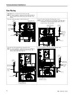
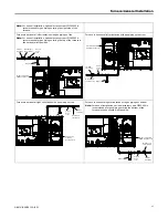
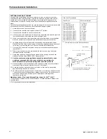
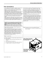
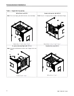
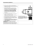
The furnace is shipped standard for left side installation of gas piping.
A cutout with plug is provided on the right side for an alternate gas
piping arrangement.
The installation of piping shall be in accordance with piping codes and
the regulations of the local gas company. Pipe joint compound must be
resistant to the chemical reaction with liquefied petroleum gases.
Important:
If local codes allow the use of flexible gas appliance
connector, always use a new listed connector. Do not use
a connector which has previously serviced another gas
appliance.
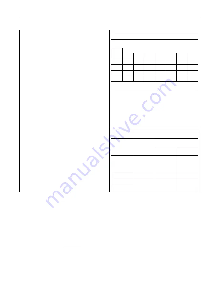
Refer to the piping table for delivery sizes. Connect gas supply to the
unit, using a ground joint union and a manual shut-off valve. National
codes require a condensation drip leg to be installed ahead of the gas
valve.
The furnace and its individual shut-off valve must be disconnected
from the gas supply piping system during any pressure testing of that
system at test pressures in excess of 1/2 psig (3.5 kPa).
The furnace must be isolated from the gas supply piping by closing its
individual manual shut-off valve during any pressure testing of the
gas supply piping system at test pressures equal to or less than 1/2
psig (3.5 kPa).
Note:
Maximum pressure to the gas valve for natural gas is 13.8" W.
C. Minimum pressure is 5.0" W.C. Maximum pressure to the
gas valve for propane is 13.8" W.C. Minimum pressure is 11.0"
W.C.
NATURAL GAS ONLY
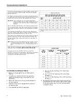
TABLE OF CUBIC FEET PER HOUR OF GAS
FOR VARIOUS PIPE SIZES AND LENGTHS
PIPE
SIZE
LENGTH OF PIPE
10
20
30
40
50
60
70
1/2
131
90
72
62
55
50
46
3/4
273
188
151
129
114
104
95
1
514
353
284
243
215
195
179
1–1/4
1060
726
583
499
442
400
368
This table is based on Pressure Drop of 0.3 inch W.C. and 0.6 SP.
GR. Gas
All gas fittings must be checked for leaks using a soapy solution before
lighting the furnace.
DO NOT CHECK WITH AN OPEN FLAME!
For propane conversions, the A801X026A will require LP kit
BAYLPSS410* conversion kit with stainless steel burners. For propane
conversions on all other S-Series Furnaces, use BAYLPSS400*
conversion kit with stainless steel burners.
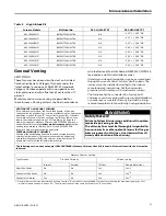
ORIFICE SIZES
INPUT
RATING
BTUH
NUMBER OF
BURNERS
MAIN BURNER ORIFICE
DRILL SIZE
NAT. GAS
PROPANE
GAS
26,000
2
51
59
40,000
2
45
56
60,000
3
45
56
80,000
4
45
56
100,000
5
45
56
120,000
6
45
56
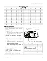
Combustion and Input Check
1. Make sure all gas appliances are off except the
furnace.
2. Clock the gas meter with the furnace operating
(determine the dial rating of the meter) for one
revolution.
3. Match the "Sec" column in the gas flow table with
the time clocked.
4. Read the "Flow" column opposite the number of
seconds clocked.
5. Use the following factors if necessary:
a. For 1 Cu. Ft. Dial Gas Flow CFH = Chart Flow
Reading ÷ 2
b. For 1/2 Cu Ft. Dial Gas Flow CFH = Chart Flow
Reading ÷ 4
c. For 5 Cu. Ft. Dial Gas Flow CFH = 10X Chart Flow
Reading ÷ 4
6. Multiply the final figure by the heating value of the
gas obtained from the utility company and compare
to the nameplate rating. This must not exceed the
nameplate rating.
Содержание A801X026AM2SC
Страница 14: ...14 A801X SVX001 1A EN Outline Drawing...

