Trane 2TTB3 Series Скачать руководство пользователя страница 3

18-BC56D1-5

3

Installer’s Guide

lines with dry nitrogen to 150 psi.  Use soap bubbles or other
leak-checking methods to see that all field joints are leak-
free!  If not, 

release pressure

; then repair!

SYSTEM EVACUATION

1. Upon completion of leak check, evacuate the refrigerant

lines and indoor coil before opening the gas and liquid
line valves.

2. Attach appropriate hoses from manifold gauge to gas

and liquid line pressure taps.

NOTE:
Unnecessary switching of hoses can be avoided and
complete evacuation of all lines leading to sealed system
can be accomplished with manifold center hose and
connecting branch hose to a cylinder of HCFC-22 and
vacuum pump.

3. The outdoor unit ships with a holding charge of dry

nitrogen. The nitrogen should be removed and the entire
system must be evacuated.  Remove the refrigerant
connection seal caps and open the service gas and liquid
valves slowly to release the nitrogen from the unit.

NOTE:
A 3/16" Allen wrench is required to open liquid line service
valve.  A 1/4" Open End or Adjustable wrench is required to
open gas line valve.  A 3/4" Open End wrench is required to
take off the valve stem cap.

4. Attach center hose of manifold gauges to the vacuum

pump once the nitrogen pressure has been relieved.

5. Evacuate until the micron gauge reads no higher than

350 microns.

6. Close off valve to vacuum pump and observe the micron

gauge. If gauge pressure rises above 500 microns in one (1)
minute, then evacuation is incomplete or system has a leak.

7. If vacuum gauge does not rise above 500 microns in

one (1) minute, the evacuation should be complete.

8. With vacuum pump and micron gauge blanked off,

weigh in HCFC 22 refrigerant based on the outdoor
unit data plate and refrigerant line set length adjust-
ments noted on page 1 of the Service Facts.

9. Close valve on HCFC-22 supply cylinder when the

appropriate refrigerant charge has been achieved.

10. Replace gas and liquid service caps.  These caps 

MUST

BE REPLACED

 to prevent leaks.  Replace caps by

finger tightening, then tighten an additional 1/6 turn.

If refrigerant lines are longer than 15 feet and/or a
different size than recommended, it will be necessary to
adjust system refrigerant charge upon completion of
installation. See page 6 or in the unit Service Facts.

D. ELECTRICAL CONNECTIONS

WARNING

!

When installing or servicing this equipment, ALWAYS
exercise basic safety precautions to avoid the possibility of
electric shock.

1. Power wiring and grounding of equipment must comply

with local codes.

2. Power supply must agree with equipment nameplate.

3. Install a separate disconnect switch at the outdoor unit.

4. Ground the outdoor unit per local code requirements.

5. Provide flexible electrical conduit whenever vibration

transmission may create a noise problem within the
structure.

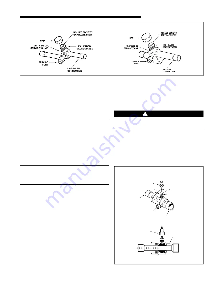
LIQUID LINE SERVICE VALVE

3

CAP

1/4 TURN ONLY
COUNTERCLOCKWISE
FOR FULL OPEN 
POSITION

VALVE STEM

GAS LINE CONNECTION

UNIT SIDE
OF VALVE

CAP

BODY

COOLING

CORE

PRESSURE TAP PORT

GAS LINE BALL SERVICE VALVE

4

GAS LINE SERVICE VALVE

Содержание 2TTB3 Series

Страница 1: ...d manufactured to withstand and operate in severe winter conditions However there are precautionary steps which should be taken at the time of installation which will help assure the efficient operation of the unit It is recommended that these precautions be taken for units being installed in areas where snow accumulation and prolonged below freezing temperatures occur 1 Units should be elevated 3...

Страница 2: ...f rated line set C SERVICE VALVE OPERATION BRASS LIQUID AND GAS LINE SERVICE VALVES The Brass Liquid and Gas Line Service Valves are factory shipped in the seated position to hold factory nitrogen charge The pressure tap service port when depressed opens only to the field brazing side of the valve when the valve is in the seated position The liquid line valve is not a back seating valve see WARNIN...

Страница 3: ...500 microns in one 1 minute then evacuation is incomplete or system has a leak 7 If vacuum gauge does not rise above 500 microns in one 1 minute the evacuation should be complete 8 With vacuum pump and micron gauge blanked off weigh in HCFC 22 refrigerant based on the outdoor unit data plate and refrigerant line set length adjust ments noted on page 1 of the Service Facts 9 Close valve on HCFC 22 ...

Страница 4: ...ost initiates DEFROST CONTROL CHECKOUT Normal operation requires a LED on board flashing 1 time second b 24V AC between R B c 24V AC between Y B with unit operating d Defrost initiation when FRC_DFT pin is shorted to TEST_COMMON pin If a defrost control problem is suspected refer to the service information in control box F COMPRESSOR START UP After all electrical wiring is complete SET THE THERMO ...

Страница 5: ... O R M E R C O N T A C T O R C O I L L O W V O L T A G E F U S E S T U C K C O M P R E S S O R I N E F F I C I E N T C O M P R E S S O R R E F R I G E R A N T U N D E R C H A R G E R E F R I G E R A N T O V E R C H A R G E E X C E S S I V E E V A P L O A D N O N C O N D E N S A B L E S R E S T R I C T E D O D A I R F L O W O D A I R R E C I R C U L A T I O N T X V S T U C K O P E N S U P E R H E A...

Страница 6: ...it nameplate 7 Locate this value in the appropriate column of the Subcooling Charging Table Locate your liquid line temperature in the left column of the table and the intersecting liquid line pressure under your nameplate subcool value column Add refrigerant to raise the pres sure to match the table or remove refrigerant to lower the pressure Again wait 20 minutes for the system conditions to sta...

Страница 7: ...8 152 6 98 3 7 8 219 8 5 8 86 3 3 8 508 20 2TWB3060A 4 1 1045 41 1 8 946 37 1 4 870 34 1 4 1 1 8 3 8 152 6 98 3 7 8 219 8 5 8 86 3 3 8 508 20 MODELS BASE FIG A B C D E F G H J K 2TTB3018A 2 2 651 25 5 8 724 28 1 2 651 25 5 8 5 8 1 4 127 5 57 2 1 4 181 7 1 8 44 1 3 4 457 18 2TTB3024A 2 2 832 32 3 4 724 28 1 2 651 25 5 8 3 4 5 16 137 5 3 8 65 2 5 8 210 8 1 4 57 2 1 4 457 18 2TTB3030A 3 2 832 32 3 4 ...

Страница 8: ...nry been sealed If mortar is used prevent mortar from coming into direct contact with copper tubing 5 Verify tightness of all electrical connects 6 Observe outdoor fan during on cycle for clearance and smooth operation 7 Indoor coil drain line drains freely Pour water into drain pan 8 Supply registers and return grilles open and unobstructed 9 Return air filter installed 10 Thermostat thermometer ...

Отзывы: