background image

WARNING

!

This information is intended for use by individuals possess-
ing adequate backgrounds of electrical and mechanical 
experience. Any attempt to repair a central air conditioning 
product may result in personal injury and/or property dam-
age. The manufacturer or seller cannot be responsible for 
the interpretation of this information, nor can it assume any 
liability in connection with its use.

WARNING

!

LIVE ELECTRICAL COMPONENTS!
During installation, testing, servicing, and troubleshoot-
ing of this product, it may be necessary to work with live 
electrical components. Failure to follow all electrical safety 
precautions when exposed to live electrical components 
could result in death or serious injury.

07/12

ALL phases of this installation must comply with NATIONAL, STATE AND LOCAL CODES

IMPORTANT — This Document is customer property and is to remain with this unit.  

These instructions do not cover all variations in systems or provide for every possible contingency to be met in connection with 
the installation. Should further information be desired or should particular problems arise which are not covered sufficiently for the 
purchaser’s purposes, the matter should be referred to your installing dealer or local distributor.

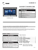
TZONE950AC52ZA

ComfortLink

™ 

II Installation Guide

Other Installation Guides may be necessary, based on system configuration.

A complete list of other optional components is shown below.

1 Control

2

Relay Panel
For use with 24V indoor systems 

(optional)

3

Zone Panel

 (optional)

4

Zone Sensor with Display

 (optional)

5

Zone Sensor

 (optional)

6

Zone Dampers

 (optional)

18-HD64D1-4

Table of Contents

Section 1. Safety ................................................1
Section 2. General Information .........................2
Section 3. Physical Installation ........................4
Section 4. Wiring ................................................6
Section 5. System Setup ...................................9
Section 6. Advanced Features ........................15
Section 7. Troubleshooting .............................19

NOTE:  See the User’s Guide for 
 

wireless setup information.

Section 1. Safety

Содержание 18-HD64D1-4

Страница 1: ...d is to remain with this unit These instructions do not cover all variations in systems or provide for every possible contingency to be met in connection with the installation Should further information be desired or should particular problems arise which are not covered sufficiently for the purchaser s purposes the matter should be referred to your installing dealer or local distributor TZONE950A...

Страница 2: ...ion Indoor Temperature Display Range 20 F to 119 F Outdoor Temperature Display Range 31 F to 119 F Indoor Humidity Display Range 0 to 99 1 resolution Minimum Cycle Off Time Delay Compressor 5 minutes Indoor Heat 1 minute The ComfortLink II Control is a communicating 7 inch color touch screen that provides an easy to use interface to the end user The Control is a communicating wall mounted control ...

Страница 3: ...ensor ZZSENSAL0400AA Control TZONE950AC52ZA Control TZONE950AC52ZA Can alternatively be connected to the Relay Panel Can alternatively be connected to the 950 Control Outdoor Unit Indoor Unit Relay Panel BAY24VRPAC52D Relay Panel Outdoor Unit Indoor Unit Communicating System 24V System Optional Wired Remote Sensor ZZSENSAL0400AA Wired Remote Outdoor Sensor BAYSEN01ATEMPA Optional Wired Remote Sens...

Страница 4: ...ic emissions from other devices appliances or wiring can interfere with the control s communication i e wireless phones security systems wireless inter net cameras Do not mount the control in recessed areas near metal objects or near structures i e doors appliances entertainment centers or shelving units Do not mount the control closer than 2 inches to any pipes duct work or other metal obstructio...

Страница 5: ...n screws to avoid damaging the sub base 1 Press tip of SnapSkru an chor into drywall using 2 Phillips screwdriver or screw gun Drive anchor clockwise into drywall until anchor stops flush with wall 2 Place sub base over anchor and insert screw 3 Tighten screw flush with sub base Screw pops open anchor locking anchor on wall Do not overtighten screws to avoid damaging the sub base If mounting to dr...

Страница 6: ... gauge color coded thermostat cable for proper wiring Shielded cable is not typically required Keep this wiring at least one foot away from large inductive loads such as Electronic Air Cleaners motors line starters lighting bal lasts and large distribution panels Failure to follow these wiring practices may introduce electrical interference noise which can cause erratic system operation All unused...

Страница 7: ...municating Indoor Unit Communicating Outdoor Unit Communicating Indoor Unit excluding TAM8 Relay Panel Red Brown Blue B D R B D R Indoor Unit 24V Outdoor Unit Relay Panel See Relay Panel Installer s Guide for specific wiring instructions Neatly bundle all low voltage wires behind the service valve cover as shown Control Control Control Red Brown Blue Red Brown Blue B D R 24V Single Stage Cooling H...

Страница 8: ...eat Pump Outdoor Unit W1 W2 W3 G Y2 B O BK D Y1 R Yellow Yellow Blue Blue Communicating Indoor Unit excluding TAM8 See Relay Panel Installer s Guide for specific wiring instructions Relay Panel Red Brown Blue B D R B D R B D R Relay Panel Variable Speed Furnace or Air Handler W1 W2 W3 G Y2 B O BK D Y1 R Neatly bundle all low voltage wires behind the service valve cover as shown Air Handler with CC...

Страница 9: ...re details Power Up Sequence When the 950 Control is connected to the Sub Base the Control will initiate a 90 120 second power up sequence During the power up sequence the Screen Calibration option is available for five seconds If the screen is not pressed within five seconds the 950 Control will default to previously stored Screen Calibration settings Note The 950 Control is factory calibrated an...

Страница 10: ...dvanced Settings 5 2 2 ADVANCED EQUIPMENT Compressor Cooling Cycles Per Hour 2 3 4 5 or 6 1st Stage Compressor Heating Cycles Per Hour 2 3 4 5 or 6 2nd Stage Compressor Heating Cycles Per Hour 2 3 4 5 or 6 Compressor Heating Cycles Per Hour 2 3 4 5 or 6 1st Stage Compressor Cooling Cycles Per Hour 2 3 4 5 or 6 2nd Stage Compressor Cooling Cycles Per Hour 2 3 4 5 or 6 Compressor Minimum On Time Min...

Страница 11: ...Control Options Stand Alone Operation Dehumidifier Operation with Active Call for Cooling Only Dehumidifier Run System Fan with Dehumidifier Request No Yes UV Light Installed None Yes Ventilation Installed Yes No Ventilation Select Relay Panel Aux Contacts Aux 1 Aux 2 Ventilation Minimum Outdoor Temperature Allowed 10F 50F Ventilation Maximum Outdoor Temperature Allowed 80F 110F Minimum Ventilatio...

Страница 12: ... Compressor Heating No Delay 1 5 Minutes 100 45 Seconds 100 30 Seconds 50 1 5 Minutes 50 3 Minutes 50 30 seconds 35 Non VS Blower On Delay Cooling No Delay 15 Seconds 30 Seconds 90 Seconds Non VS Blower Off Delay Cooling No Delay 30 Seconds 60 Seconds 90 Seconds Non VS Blower On Delay Compressor Heating No Delay 15 Seconds 30 Seconds Non VS Blower Off Delay Compressor Heating No Delay 30 Seconds 6...

Страница 13: ...low Capacity Adjustment Normal More Aggressive Less Aggressive Airflow Capacity of Total 25 100 Voting Zones No Yes Indoor Heating Airflow Offset above and below cooling airflow 50 50 0 Discharge Temperature Limit Cooling Normal 38 Extended 34 Discharge Temperature Limit Compressor Heating Only Normal 116 Extended 128 Discharge Temperature Limit Compressor Heating w Aux Heat Normal 160 Extended 17...

Страница 14: ...el When a wired sensor is connected to Zone 1 slot of the Zone Panel two actions occur 1 The wired sensor connected to Zone 1 slot is auto enabled as Zone 1 2 The onboard temperature sensor and onboard humidity sensor of the 950 Control is disabled a The onboard humidity sensor can be re enabled by navigating to the Installer Settings Advanced Sensors Thermostat Humidity Sensor Enable b If a wired...

Страница 15: ... closed and moved to the top right corner of the control Major Alerts indicates the loss of system functionality but the system is still operational Major alerts will be displayed as a solid yellow icon in the upper right corner of the control Blower On Off Delays Blower on off profiles can be set independently for heating and cooling modes There are blower delays specific for variable speed non v...

Страница 16: ...PF of the heat pump and AFUE of the furnace must be entered along with cost of electricity and fuel The control calculates an economic balance point for system change over Outdoor Temperature The changeover from heat pump to furnace is based on outdoor tem perature which can be set from 0 70 thermal balance point The furnace will take over anytime the HP is unable to maintain indoor temperature re...

Страница 17: ...tages above a set outdoor tempera ture from 40 70 This value must be set higher than the compressor heating lockout Defrost Heater Balance Point for W1 W2 W3 will lock out specific auxiliary heat stages when above a set outdoor temperature W1 setpoint is from 40 55 W2 W3 setpoints are from 5 55 This feature does not apply to dual fuel systems Compressor Cooling First Stage Lockout will lock out th...

Страница 18: ...grade Insert SD Card and use the software upgrade screen to complete the upgrade process System Report The System Report Screen provides a real time in depth look at operating conditions While similar to the System Status screen the system report adds additional information for service technicians Test Mode There are two Test Modes in the control System Test Ability to test heating cooling blower ...

Страница 19: ...g is displayed but no warm or cool air is coming from the registers 1 There is a fan delay as the heating or cooling equipment turns on 2 Equipment is not working properly 1 Wait a minute for blower delays and recheck registers 2 Check repair system Fan runs all the time 1 Fan mode is set to On Circulate or Clean mode 2 There is a failure in the indoor unit 1 Check Control settings to see if fan i...

Страница 20: ...of continuous product and product data improvement and it reserves the right to change design and specifications without notice Representative only illustrations included in this document 6200 Troup Highway Tyler TX 75707 2012 Trane ...

Отзывы: