background image

TracVision R5SL/R4SL

3

RF PCB Replacement Instructions

c.

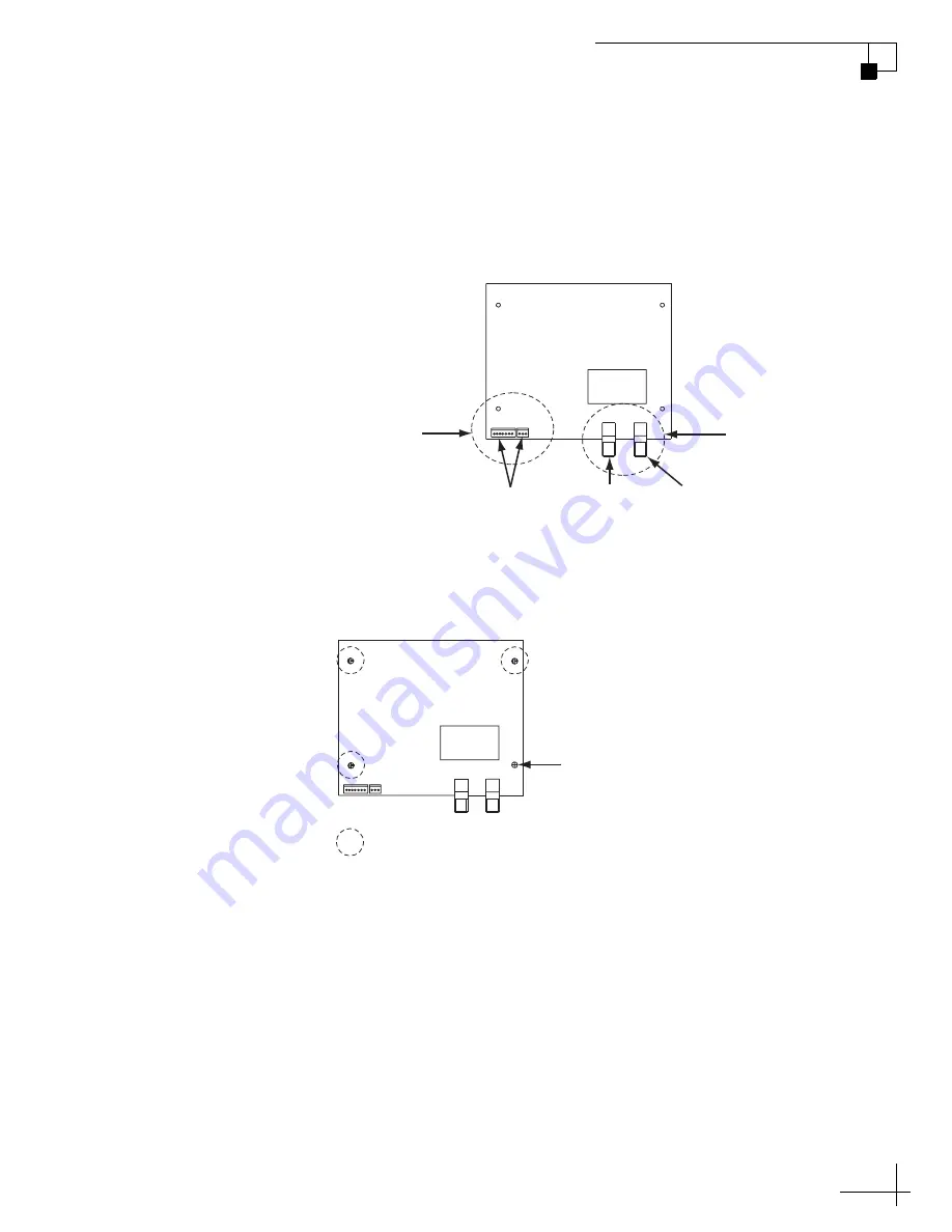
Disconnect the two Molex connectors from the RF PCB. 

Using a 7/16" open-end wrench, disconnect the two RF 

connectors from the RF PCB. Tag the RF cables first to 

ensure they are returned to the correct connectors on 

the new RF PCB.

Figure 3  RF PCB Connectors

d.

Using a #1 Phillips screwdriver, remove the screw 

securing the RF PCB to the rotating plate.

Figure 4  RF PCB Screw and Standoffs

RF PCB

RF
Connectors

Molex

Connectors

From

Main PCB

To

Receiver

To
LNB

J6

J4

T

O

 IRD

FR

OM LNB

RF PCB

J6

J4

T

O

 IRD

FR

OM LNB

Screw

= Standoffs (x 3)

Содержание R4SL

Страница 1: ...gh the KVH Partner Portal at www kvh com partners 1 Phillips screwdriver 2 Phillips screwdriver 7 16 open end wrench Needle nose pliers PC with the latest version of the Flash Update Wizard installed Be sure to avoid causing sharp bends in cables when securing or rerouting cables in the following procedures Sharp bends or kinks in cables can degrade antenna performance IMPORTANT CAUTION For your o...

Страница 2: ...emove the radome and set it aside in a safe place Figure 1 Radome Screws b Using a 1 Phillips screwdriver remove the screw securing the RF PCB cover to the rotating plate Then remove the cover NOTE The RF PCB is static sensitive Ensure that you take the necessary grounding precautions before handling Figure 2 RF PCB Cover RF PCB Radome Screws RF PCB RF PCB Cover RF PCB Cover Screw ...

Страница 3: ...g the RF cables first to ensure they are returned to the correct connectors on the new RF PCB Figure 3 RF PCB Connectors d Using a 1 Phillips screwdriver remove the screw securing the RF PCB to the rotating plate Figure 4 RF PCB Screw and Standoffs RF PCB RF Connectors Molex Connectors From Main PCB To Receiver To LNB J6 J4 TO IRD FROM LNB RF PCB J6 J4 TO IRD FROM LNB Screw Standoffs x 3 ...

Страница 4: ... NOTE Excessive force can damage the PCB standoffs Be sure to gently depress the standoff tab then carefully raise the PCB over the standoff tab Figure 5 PCB Standoff f Remove the RF PCB g Reverse this procedure to install the replacement RF PCB Ensure that the cable connectors are returned to their original positions Then reinstall the radome and reconnect power to the TracVision system Standoff ...

Страница 5: ...P If your computer does not have a DB9 serial COM port you can use a KVH tested USB adapter Refer to the Flash Update Wizard s Release Notes for more information Figure 6 TracVision Switchplate b Double click the KVH Flash Update Wizard shortcut on your PC s desktop to start the Flash Update Wizard TIP You do not need to flash the antenna you will simply type commands in the Flash Update Wizard s ...

Страница 6: ...es not match the software version listed in the Release Notes proceed to Step 3 Flash the Main PCB if required Step 3 Flash the Main PCB if required The main PCB now needs to be updated or flashed to ensure compatibility with the new RF PCB Flashing also allows the antenna to use the most current satellite configuration data available Follow the Flash Update Wizard instructions to flash the main b...

Отзывы: