TracPhone v7ip Скачать руководство пользователя страница 27

24

Follow these steps to customize the web interface 
for the customer’s use.

Set the Administrator Password

The user must be logged in as an administrator to 
make changes to the system’s configuration. 
Follow these steps to change the administrator 
password to something unique.

a.

At the TracPhone V7-IP web interface, click 

the

 Settings

 tab. Then click 

Account

.

b.

In Security, click 

Edit

.

c.

For the current password, enter the default 

password: “

password

” (see Figure 36).

d.

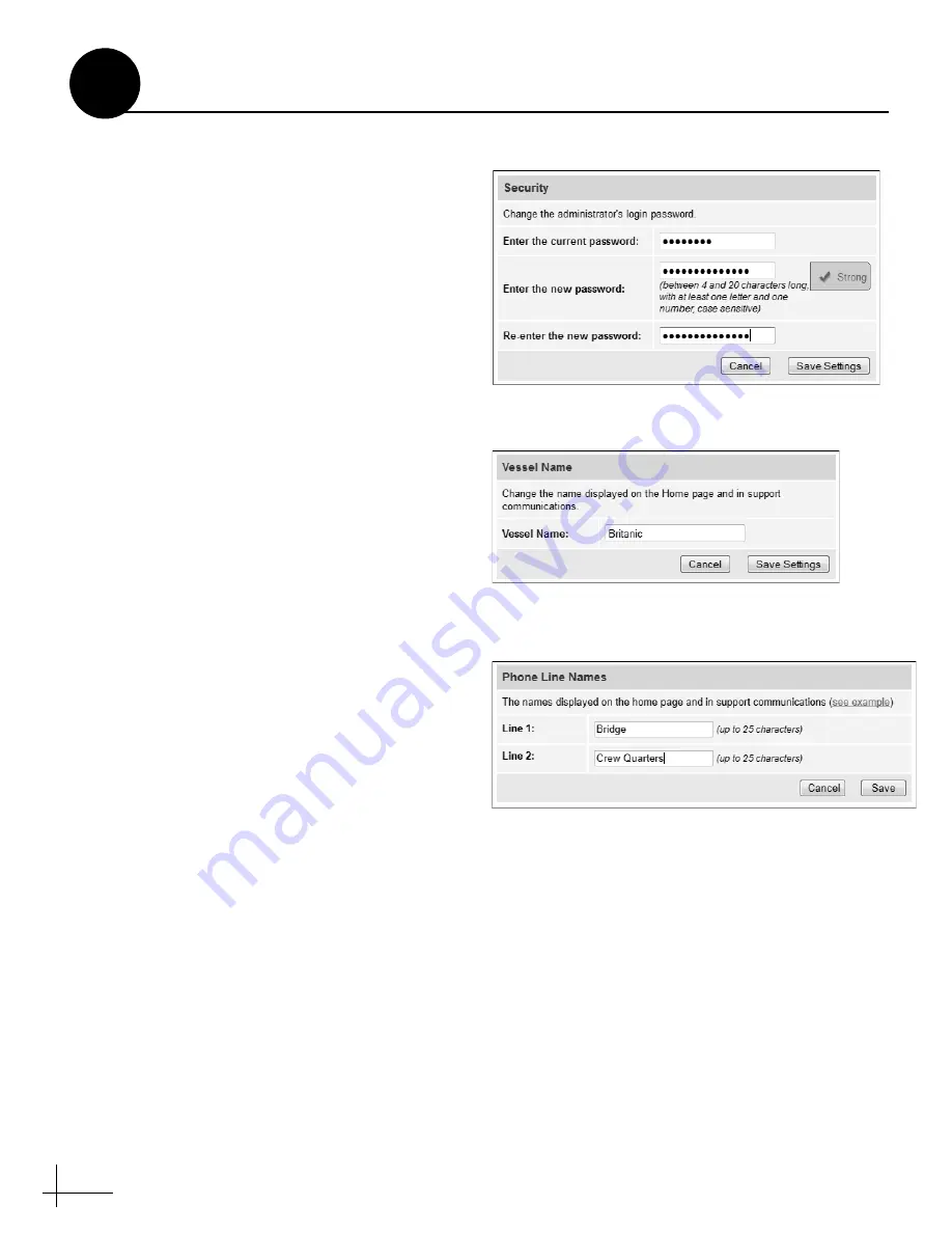
Enter and then re-enter the new password. 

Then click 

Save Settings

.

Enter the Vessel Name

The vessel name is displayed on the home page 
and in all support communications. Follow these 
steps to enter the correct vessel name.

a.

At the TracPhone V7-IP web interface, click 

the

 Settings

 tab. Then click 

Account

.

b.

In Vessel Name, click 

Edit

.

c.

Enter the vessel name (see Figure 37). Then 

click 

Save Settings

.

Assign Phone Line Names

The phone line names are displayed on the home 
page and in all support communications. Follow 
these steps to assign a name (i.e., location) to each 
phone line.

a.

At the TracPhone V7-IP web interface, click 

the

 Settings

 tab. Then click 

Other

.

b.

In Phone Line Names, click 

Edit

.

c.

Enter names for Lines 1 and 2 (see Figure 38). 

Then click 

Save

.

Figure 36:  Setting the Administrator Password

Figure 37:  Entering the Vessel Name

Figure 38:  Assigning Phone Line Names

Customize the Web Interface

14

Содержание v7ip

Страница 1: ...Installation Guide TracPhone V7IP 26 66 cm Configuration...

Страница 2: ...Antenna section should read as follows e Tighten all four bolts until the four rubber feet on the baseplate are bottomed against the mounting surface and the foam seal is fully compressed KVH recomme...

Страница 3: ...the base of the cable shroud as shown in Figure 1 Figure 1 Power Data Cable Shroud c Secure the end of the power data cable to the base of the shroud using the supplied clamp This clamp will help rel...

Страница 4: ...d a technician near you visit www kvh com wheretogetservice Technical Support 1 Inspect Parts and Get Tools 3 2 Plan the Antenna Installation 4 3 Plan the Belowdecks Installation 6 4 Prepare the Below...

Страница 5: ...lity The TracPhone V7 IP system provides broadband Internet connectivity between a ship and any destination in the world The equipment is not intended for SOLAS applications Declaration and Certificat...

Страница 6: ...lant self vulcanizing tape or equivalent Heat gun for heat shrink Eye protection Shop towels Voltmeter Utility knife Flush cutters Radome Antenna KVH part 02 1925 SL Baseplate CommBox ACU KVH part 02...

Страница 7: ...ic compasses or other onboard antennas to prevent potential interference Radar High Power Radio Transmitters Although many variables determine the exact distance required between the antenna and radar...

Страница 8: ...in an elevation range of 15 to 15 see Figure 4 Therefore mount the antenna outside this elevation range and at least 10 ft 3 m away from the transmitter Antenna Antenna 15 15 Potential RF Interference...

Страница 9: ...82 6 mm rack occupying 3U of space To use the supplied power data cable the CommBox ACU must be located within 100 ft 30 m of the antenna However you can order a 150 ft 45 m cable if a longer cable ru...

Страница 10: ...ACU modem assembly and secure the front mounting brackets to the case using four M6 screws and washers see Figure 9 i Secure the back of the CommBox ACU to the back of the case using the two supplied...

Страница 11: ...ps and modem using the screws and washers you removed in Step a see Figure 10 c Insert the CommBox ACU modem assembly into the rack and secure the front mounting brackets to the rack using four M6 scr...

Страница 12: ...he screws and washers you removed in Step a see Figure 12 c Attach the supplied L mounting brackets to the sides of the modem using four 6 32 screws and washers see Figure 13 d Once you have completed...

Страница 13: ...bolts through these holes to secure the antenna to the mounting surface d Cut out the 3 75 95 mm cable access hole in the location you marked in Step b Smooth the edges of the hole to protect the cabl...

Страница 14: ...embly slowly by hand to reveal the other two 1 2 shipping bolts Remove these bolts e Transport the antenna to the mounting location NOTE The two hoisting eyelets on the antenna frame may be used to li...

Страница 15: ...K 400EZ 75 KVH part no 72 0374 75 Strip Lengths 101 150 ft 31 45 m Cable Run Cable LMR 600 75 KVH part no 32 0945 0150 Loss 0 04 dB ft 0 13 dB m Connector Times Microwave EZ 600 FMH 75 Tools Times Mic...

Страница 16: ...s RF cables and the pigtail cables Slide a heat shrink sleeve onto the end of each 3 ft 90 cm pigtail cable opposite the boot end for later use c Fill half of the inner body of the customer s TX RF c...

Страница 17: ...with silicone grease d Connect and SLOWLY hand tighten the TX pigtail cable to the antenna s MTx jack allowing the grease to diffuse and settle into the entire space within the connector e Make sure...

Страница 18: ...s near the antenna connectors to relieve stress see Figure 22 b Weatherproof and seal the cable access hole as required Strain relief Figure 22 Strain relief Example The integrity and reliability of t...

Страница 19: ...the safety warnings printed on the tube of Loctite anti seize lubricant Contains mineral oil calcium hydroxide and copper May cause skin eye and respiratory irritation Wear eye protection and gloves F...

Страница 20: ...med against the mounting surface and the foam seal is fully compressed KVH recommends that you tighten the nuts to between 35 and 40 ft lbs 47 and 54 N m of torque f Reinstall the radome onto the ante...

Страница 21: ...EN 1000 Fuse 3A 250V Fast Acting N WiFi Antenna Terminal Strip Connector 1 2 11 10 9 8 7 6 12 5 4 3 13 14 15 16 Blue White White Blue Brown White White Gray Gray White White Orange Orange White White...

Страница 22: ...re the RF cables are terminated properly with type F connectors IMPORTANT AC Input 100 240V 1 6 0 8A 50 60 Hz Maintenance RS232 To Modem RS422 NMEA 1 2 0 WiFi 1 2 3 4 Voice Lines Analog User Ethernet...

Страница 23: ...rrent is unacceptable KVH recommends that you install a suitable isolation transformer to supply single phase power to the antenna system and run a ground wire from the transformer to ship s ground In...

Страница 24: ...ial between chassis ground and ship s ground to make certain that there is no dangerous floating ground condition even if the ground pin of the vessel s AC power plug appears to be intact AC Input 100...

Страница 25: ...for 30 minutes to allow the modem to download the latest SSCF SED configuration files via the satellite If the modem is unable to connect you may upload these files manually via the modem s web inter...

Страница 26: ...the software using the TracPhone V7 IP web interface However you can also update the software using the mini VSAT iPhone iPod Touch app a USB drive or if the system is activated via the antenna s Int...

Страница 27: ...d on the home page and in all support communications Follow these steps to enter the correct vessel name a At the TracPhone V7 IP web interface click the Settings tab Then click Account b In Vessel Na...

Страница 28: ...hs that define the outer boundaries of the zone s relative to the antenna s forward arrow which should be pointing toward the bow see Figure 40 b Determine the necessary elevation range for each no tr...

Страница 29: ...sure Enforce Zones is selected see Figure 42 f Enter the azimuth and elevation ranges for Zone 1 g Enter the azimuth and elevation ranges for Zone 2 if required h Click Save Settings i At the confirm...

Страница 30: ...installation checklist provided in the Customer Welcome Kit and return it to KVH Refer to the instructions on the form Figure 43 Good Service Connection Indicated on Home Page Figure 44 Heading Displ...

Страница 31: ...e page 36 b At the TracPhone V7 IP web interface click the Settings tab Then click Network Settings To Modem RS422 1 2 0 WiFi 1 2 3 4 Voice Lines Analog User Ethernet Ports Ethernet To Modem BUC Power...

Страница 32: ...he air b Connect the static IP device to the User Ethernet 4 port on the CommBox ACU c The customer will need to configure the device s TCP IP properties according to the instructions KVH will provide...

Страница 33: ...ustomer to select install and configure the appropriate bundle to meet their needs Figure 51 Connecting Vessel Phones Example AC Input 100 240V 1 6 0 8A 50 60 Hz Maintenance RS232 To Modem RS422 NMEA...

Страница 34: ...s see Figure 54 Clean the antenna regularly Dirt buildup on the radome can affect communications Heavy rain or snow may also temporarily interrupt communications The vessel must be located within the...

Страница 35: ...pliers see Figure 57 Also make sure the center conductor is centered within the cable 3 Place the heat shrink sleeve and metal ferrule onto the cable see Figure 58 4 Insert the end of the cable into t...

Страница 36: ...l the tool turns easily This removes the cable jacket from the end of the cable exposing the braid and dielectric see Figure 62 7 Using the DBT 02 tool deburr and chamfer the center conductor see Figu...

Страница 37: ...ide of the connector 10 Trim any excess braid see Figure 66 if necessary The braid should assemble flush to within 1 16 1 6 mm of the connector shoulder 11 Slide the ferrule over the braid until it is...

Страница 38: ...place see Figure 69 When you are done the heat shrink should extend from the rear of the connector to the cable jacket This forms a weather tight seal 15 Using a multimeter or similar device check the...

Страница 39: ...and Sharing Center window double click the Local Area Connection link Windows 7 or View Status link Windows Vista for the Ethernet connection you are using 4 At the Local Area Connection Status window...

Страница 40: ...he computer is currently connected to a network 5 At the Local Area Connection Properties window click the General tab Then select Internet Protocol TCP IP and click Properties see Figure 73 6 At the...

Страница 41: ...rences click Network 3 In the Network dialog box select Ethernet then set the following Location Automatic Configure IPv4 Using DHCP 4 Click Apply 5 Restart the computer Figure 75 Macintosh OS X Netwo...

Страница 42: ...tandards CAUTION RISK OF ELECTRIC SHOCK DO NOT OPEN 1000 Fuse 3A 250V Fast Acting N WiFi Power Power J1 AC PWR J3 Rx RF J2 Tx RF J4 ACU J5 CONSOLE J6 BUC PWR J8 USER ENET J7 ACU ENET NO OPERATOR SERVI...

Страница 43: ...847 3327 Fax 1 401 849 0045 E mail info kvh com KVH Industries A S EMEA Headquarters Kokkedal Denmark Tel 45 45 160 180 Fax 45 45 160 181 E mail info emea kvh com KVH Industries Pte Ltd Asia Pacific H...

Отзывы: