


R-
NET
T
ECHNICAL
M
ANUAL
- O
PERATION
PG D
RIVES
T
ECHNOLOGY
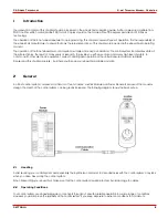
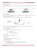
4.2.11 External Profile Switch Jack
This allows the user to select Profiles using an external device, such as a buddy button.
To change the Profile whilst driving simply press the button.
If the control system is set to latched drive or actuator control operation, then the polarity of the jack input is reversed to effect a
fail safe system; meaning this input will provide an External Profile Switch function and an Emergency Stop Switch function.
The Joystick Module is supplied with rubber bungs that must be inserted into the Jack Socket
when no external device is connected.
4.3 LCD
Screen
The status of the control system can be understood by observing the LCD screen. The control system is on when the screen is
backlit.
Refer to section 5 for details on screen symbols.
4.5 Charger
Socket
This socket should only be used for charging or locking the wheelchair. Do not connect any type of programming cable into this
socket.
Refer to section 10 for more details on charging.
This socket should not be used as a power supply for any other electrical device. Connection of other electrical devices may
damage the control system or affect the E.M.C. performance of the wheelchair.
The control system’s warranty will be voided if any device other than a battery charger supplied,
with the wheelchair, or the lock key is connected into this socket.
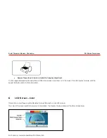
5
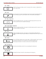
LCD Screen - Monochrome
The status of the control system can be understood by observing the LCD screen.
5.1 Screen Symbols
The Drive screen for the R-net has common components, which will always appear, and components that will only appear under
certain conditions. Below is a view of a typical Drive screen in Profile 1.
SK77981/4
18


