Printed in the Federal Republic of Germany
TR-Electronic GmbH 2018, All Rights Reserved
11/12/2019
TR - ELA - BA - DGB - 0027 - 03
Page 133 of 167
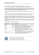
6.3.4.2.1 Header (PNU 65001.00)
The header in Subindex 0 contains the parameter structure version.
Bits
Meaning
0 - 7
0x02 (LSB)
Version no. 0x0102
8 -15
0x01 (MSB)
16 - 23
0x12
Number of indices = 18
24 - 31
reserved
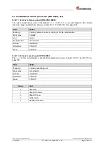
6.3.4.2.2 Operating status (PNU 65001.01)
The operating status in Subindex 1 contains the parameter settings made for the bit-coded parameters
in chapter "Configurable module parameters", see from page 117.
Bits
Definition
0
Code Sequence
1
Encoder Class 4 functionality
2
Preset affects XIST1
3
Scaling function control
4
Alarm channel control
5
Compatibility Mode V3.1
6
Encoder type, also see chapter 6.3.4.3 on page 136
0: Rotary encoder, resolution in steps per revolution
1: Linear encoder, resolution in nm per step
7 - 31
reserved
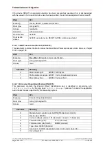
6.3.4.2.3 Error (PNU 65001.02)
The parameter in Subindex 2 displays the current measuring system errors. When an error occurs, the
corresponding bit is set and visually displayed via the device status LED. The measuring system
remains in the error state until the cause of the error has been eliminated and the error state has been
acknowledged with the control word
G1_STW
Bit 15 = 0->1 edge.
If the error cannot be acknowledged, you can try carrying out a device RESET via PNU 972. If the
error still cannot be deleted after this measure, the measuring system must be replaced.
Bits
Definition
= 0
=1
0
Position error
no
yes
1-21
Not supported
Always 0
-
22
Memory error
no
yes
23-24
Not supported
Always 0
-
25 - 31
reserved
A position error is also indicated, if e.g.
- the magnet is outside the measuring range
- the minimum distance between two magnets has not been observed
- the configured number of magnets does not match the operated number


