background image


Printed in the Federal Republic of Germany 

 TR-Electronic GmbH 2018, All Rights Reserved 

11/12/2019 

TR - ELA - BA - DGB - 0027 - 03 

Page 117 of 167 

6.3.3 Configurable module parameters 

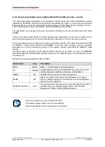
The parameters can be set according to the following table via an input mask in the configuration tool. 

The default parameters are automatically sent by the control to the measuring system during start-up 

via the record data object with index 

0xBF00

, and the manufacturer-specific parameters via the record 

data object with index 

0x0001

. The manufacturer-specific parameters can either be enabled or 

disabled. 


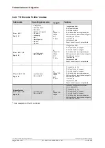
Manufacturer-specific parameters 

Byte 

Parameter 

Data type  Description 

Page 

TR Encoder 

parametrization 

Unsigned8 

Enabling of manufacturer-specific parameters 

0: disable 

1: enable


119 

Interpolation 

Unsigned8 

Measured value processing for calculation of 

additional position values 

0: disable


1: enable 

119 

Observer 

Unsigned8 

Mathematical processing of speed measured 

values 

0…7 

Default value: 

0

, no processing 

119 

Averaging 

Unsigned8 

Averaging of position values 

0…32 

Default value: 

0

, no averaging 

120 

4-5 

Option 1 

Unsigned16 

reserved 

6-9 

Option 2 

Unsigned32 

reserved 


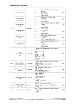
Default parameters 

Byte 

Parameter 

Data type  Description 

Page 

0-1 

Parameter 

initialization control 

Bit range 

Bit 0-1 

Parameter initialization control 

0: PRM Data Block


1: RAM data 

Class 3 and 4 

120 

Parameter write 

protection 

Bit 2-4 

Parameter access control 

0: Writable


1: Write-protected 

Class 3 and 4 

120 

Write protection for 

parameter control 

+ parameter Save 

Bit 5 

Access control for parameters PNU 

65005 and PNU 971 

0: Writable


1: Write-protected 

Class 3 and 4 

121 

Write protection for 

parameter Reset 

Bit 6 

Access control for parameter 

PNU 972 

0: Writable


1: Write-protected 

Class 3 and 4 

121 

reserved 

Bit 7-15 


reserved 


Содержание LMP-30

Страница 1: ..._Zus tzliche Sicherheitshinweise _Installation _Inbetriebnahme _Konfiguration Parametrierung _St rungsbeseitigung Diagnosem glichkeiten Absolut Linear Encoder PNO Encoder Profil V4 2 Class 3 4 TR Enc...

Страница 2: ...grafische Archivierung und Ver nderung bedarf der schriftlichen Genehmigung durch den Hersteller Zuwiderhandlungen verpflichten zu Schadenersatz nderungsvorbehalt Jegliche nderungen die dem technische...

Страница 3: ...ch bei PROFINET IO 18 5 4 Adressvergabe 19 5 5 Bus Statusanzeige 20 6 Parametrierung und Konfiguration 21 6 1 Modularer Aufbau 21 6 2 bersicht 23 6 2 1 Modul PNO Encoder Profil 23 6 2 2 Modul TR Encod...

Страница 4: ...s PNU 65001 01 49 6 3 4 2 3 Fehler PNU 65001 02 49 6 3 4 2 4 Unterst tzte Fehler PNU 65001 03 50 6 3 4 2 5 Warnungen PNU 65001 04 50 6 3 4 2 6 Unterst tzte Warnungen PNU 65001 05 50 6 3 4 2 7 Encoder...

Страница 5: ...windigkeitswerte 1 bis 30 71 6 4 2 3 Ausgangsdaten 72 6 4 2 3 1 Steuerbyte Preset Justage 72 6 4 2 3 2 Magnet Nummer 73 6 4 2 3 3 Justagewert 73 6 4 3 PROFINET Diagnose Alarm 74 7 Medienredundanz MRP...

Страница 6: ...ic of Germany Page 6 of 167 TR ELA BA DGB 0027 03 11 12 2019 nderungs Index nderung Datum Index Erstausgabe 07 02 18 00 Skalierung 50 000 nm erg nzt 04 12 18 01 Fehlercode 0x1003 mit aufgenommen 25 09...

Страница 7: ...on modular aufgebaut ist stellt dieses Benutzerhandbuch eine Erg nzung zu anderen Dokumentationen wie z B Produktdatenbl tter Ma zeichnungen Prospekte und der Montageanleitung etc dar 1 1 Geltungsbere...

Страница 8: ...ier Sense Multiple Access with Collision Detection CSMA CD Access Method and Physical Layer Specifications 5 IEEE 802 1Q IEEE Standard for Priority Tagging 6 IEEE 1588 2002 IEEE Standard for a Precisi...

Страница 9: ...enelements den Zustand gut schlecht mit Fehlerort IOPS IO Provider Status damit signalisiert der Provider eines IO Datenelements den Zustand gut schlecht mit Fehlerort IP Internet Protocol IRT Isochro...

Страница 10: ...wenn die entsprechenden Vorsichtsma nahmen nicht getroffen werden bezeichnet wichtige Informationen bzw Merkmale und Anwendungstipps des verwendeten Produkts 2 2 Erg nzende Hinweise zur bestimmungsgem...

Страница 11: ...rd f r Industrial Ethernet und deckt alle Anforderungen der Automatisierungstechnik ab PROFINET ist eine ffentlich zug ngliche Spezifikation die durch die IEC IEC PAS 62411 im Jahr 2005 ver ffentlicht...

Страница 12: ...rnet Teilnehmer gleichberechtigt am Netz agieren wird das bekannte Master Slave Verfahren bei PROFINET IO als Provider Consumer Modell umgesetzt Der Provider Mess System ist dabei der Sender der seine...

Страница 13: ...bertragung von zeitkritischen Prozessdaten unterscheidet PROFINET zwischen drei Real Time Klassen die sich hinsichtlich ihrer Leistungsf higkeit differenzieren Real Time RT Class1 RT Verwendung von St...

Страница 14: ...ELA BA DGB 0027 03 11 12 2019 3 3 Weitere Informationen Weitere Informationen zu PROFINET sind bei der Gesch ftsstelle der PROFIBUS Nutzerorganisation erh ltlich PROFIBUS Nutzerorganisation e V Haid u...

Страница 15: ...und muss nicht durch Schalter eingestellt werden Eine Adressierung ber Schalter ist ebenfalls nicht notwendig diese wird automatisch durch die Adressierungsm glichkeiten des PROFINET Controllers vorge...

Страница 16: ...schstecker M12x1 4 pol A kodiert Pin 1 19 27 V DC Pin 2 N C Pin 3 GND 0 V Pin 4 N C F r die Versorgung sind paarweise verdrillte und geschirmte Kabel zu verwenden Die Schirmung ist gro fl chig auf das...

Страница 17: ...urch das festgelegte Dateiformat kann das Projektierungssystem die Ger testammdaten des PROFINET Mess Systems einfach einlesen und bei der Konfiguration des Bussystems automatisch ber cksichtigen Die...

Страница 18: ...Daten durch einen Untersetzungsfaktor eingestellt werden Nach der Parametrierung werden die IO Daten nach einmaliger Anforderung des IO Controllers vom IO Device in einem festen Takt bertragen Zyklis...

Страница 19: ...etrieb am Ethernet noch eine IP Adresse Im Auslieferungszustand hat das Mess System die Default IP Adresse 0 0 0 0 gespeichert Wenn wie oben angegeben ein Bus Scan durchgef hrt wird wird zus tzlich zu...

Страница 20: ...g fehlt Hardware defekt Mess System defekt fehlerhafte Position Speicherfehler Normalbetrieb Datenaustausch NET Status rot gr n Bedeutung Spannungsversorgung fehlt Hardware defekt keine Verbindung zum...

Страница 21: ...ragen wird F r diese Konfiguration muss dann nur noch die gew nschte E A Adresse angegeben werden Abh ngig von der gew nschten Konfiguration kann das Mess System auf dem PROFINET eine unterschiedliche...

Страница 22: ...GB 0027 03 11 12 2019 Jedes Modul bzw Submodul belegt mehr oder weniger Ein und Ausg nge und besitzt einen Satz an Parameterdaten der entsprechend der Anwendung eingestellt werden muss Damit das Mess...

Страница 23: ...mkanal Kompatibilit tsmodus V3 1 Skalierung Aufl sung nm Skalierung Gesamtaufl sung Tolerierte Lebenszeichenfehler Geschwindigkeitseinheit Geschwindigkeits Referenzwert N2 N4 Preset value Standard Tel...

Страница 24: ...nete Betrieb 32 Bit Positionsdaten Magnet 16 Bit Geschwindigkeitsdaten Magnet 32 Bit Status und Warn Meldungen 8 Bit Anzahl parametrierte Magnete 8 Bit Lebenszyklusz hler 1 Steuerbyte 4 Byte Presetdat...

Страница 25: ...ol Applications Grunds tzlich basiert das Encoder Profil auf dem f r Antriebe spezifizierte PROFIdrive Profile Viele Begriffe und Funktionalit ten wurden daher auch auf das Encoder Profil bertragen Vo...

Страница 26: ...evice Master EW 1 EW 2 EW 3 EW 4 EW 5 EW 6 EW 7 ZSW2_ENC G1_ZSW G1_XIST1 G1_XIST2 NIST_A Struktur der Ausgangsworte 1 bis 2 Master IO Device AW 1 AW 2 STW2_ENC G1_STW 6 3 1 3 Standard Telegram 83 Stru...

Страница 27: ...0 Data 231 224 223 216 215 28 27 20 6 3 1 6 Format Signal 9 Steuerwort Sensor 1 G1_STW Das Steuerwort G1_STW steuert die grundlegenden Mess System Funktionen Unsigned16 Bit Funktion CL3 CL4 0 10 rese...

Страница 28: ...eigt den Mess System Status Quittierungen und Fehlermeldungen der grundlegenden Mess System Funktionen an Unsigned16 Bit Funktion CL3 CL4 0 10 reserviert 11 Mess System Fehlerquittierung in Bearbeitun...

Страница 29: ...ig vom bergebenen Presetwert wird die Istposition ohne Vorzeichen bzw mit Vorzeichen im Zweierkomplement angegeben Damit die Ausgabe erfolgen kann m ssen jedoch die entsprechenden Bits in den Steuerun...

Страница 30: ...ng Lebenszeichen Wird in taktsynchronen Anwendungen ben tigt Die Steuerung inkrementiert den 4 Bit Z hler in jedem Zyklus der Steuerungsanwendung G ltige Werte sind 1 bis 15 der Wert 0 bedeutet Fehler...

Страница 31: ...en E A Daten des Mess Systems sind ung ltig au er das Lebenszeichen 1 Steuerung angefordert das Automatisierungssystem wird aufgefordert die Steuerung zu bernehmen die Daten sind g ltig ja ja 10 11 re...

Страница 32: ...lich M ssen jedoch auch w hrend des Betriebs Parameter ge ndert werden ist der Parameterzugriff nach der Hochlaufphase auch ber einen azyklischen Schreib bzw Leseauftrag m glich siehe hierzu Kapitel A...

Страница 33: ...ed8 Messwertaufbereitung zur Berechnung von zus tzlichen Positionswerten 0 sperren 1 freigeben 35 2 Beobachter Unsigned8 Mathematische Aufbereitung der Geschwindigkeits Messwerte 0 7 Standardwert 0 ke...

Страница 34: ...Bit 5 Kompatibilit t zu Encoder Profil V3 1 0 freigeben 1 sperren Klasse 3 und 4 39 3 6 Skalierung Aufl sung nm Unsigned32 Die Aufl sung wird in nm Inkrement gemessen 1000 1 m 2000 2 m 5000 5 m 10 00...

Страница 35: ...interne Mess System Zykluszeit um ein vielfaches gr er ist als die Buszykluszeit kann es sinnvoll sein die Interpolation einzuschalten Empfehlung Bei Buszykluszeiten 4 ms Interpolation einschalten Dur...

Страница 36: ...reibung Default PRM Data Block 0 Mess System wird beim Hochlauf mit den Parametern aus dem Parameter Datenblock des Mess Systems initialisiert Die Einstellungen werden dabei gem Kapitel Konfigurierbar...

Страница 37: ...6 3 3 8 Schreibschutz PNU 972 Alternativ kann die Einstellung dieses Parameters auch im laufenden Betrieb ber einen azyklischen Parameterzugriff auf die Parametersteuerung PNU 65005 Bit 6 vorgenommen...

Страница 38: ...eeinflusst XIST1 auf freigeben eingestellt ist X 6 3 3 11 Preset beeinflusst XIST1 Alternativ kann die Einstellung dieses Parameters auch im laufenden Betrieb ber einen azyklischen Parameterzugriff au...

Страница 39: ...arameter Kompatibilit tsmodus V3 1 die Einstellung freigeben vorherrscht Der Mess System spezifische Alarmkanal wird als kanalbezogene Diagnose bertragen Im taktsynchronen Betrieb kann auf diese Weise...

Страница 40: ...oleriert ber PNU 925 kann jedoch die An zahl der tolerierten Fehler eingestellt werden wird unterst tzt Parameter Diagnose ber Alarmkanal wird unterst tzt wird nicht unterst tzt die profil spezifische...

Страница 41: ...Skalierung Gesamtaufl sung 0 ber die im Mess System hinterlegte Messl nge und der unter Parameter Skalierung Aufl sung nm eingestellten Aufl sung wird die Gesamtschrittzahl ber den gesamten Messberei...

Страница 42: ...ert im PROFIdrive Antriebsprofil ausgegeben Der Geschwindigkeitsistwert in den Signalen NIST_A und NIST_B ist dabei ein Prozentsatz des Parmeters Geschwindigkeits Referenzwert N2 N4 6 3 3 18 Geschwind...

Страница 43: ...Parameterzugriff auf die Presetwertfunktion PNU 65000 vorgenommen werden siehe 48 ber den Parameter Preset value kann der Nullpunkt des Mess Systems auf den mechanischen Nullpunkt angeglichen werden u...

Страница 44: ...MENS zur Verf gung gestellten Systemfunktionsbausteins SFB 53 WRREC write record ausgel st Die Record Data Response muss separat ber einen Leseauftrag mit Hilfe des Systemfunktionsbausteins SFB 52 RDR...

Страница 45: ...x42 Word 0x43 Double Word nur bei Schreibzugriff 11 Anzahl Werte Anzahl der folgenden Werte 12 Werte Tabelle 1 Record Data Request Datenformat der Record Data Response Byte Name Bedeutung 0 Request Re...

Страница 46: ...l Parameter 4 0x10 Attribut 5 0x00 Anzahl Elemente 6 0xFD PNU High Byte 7 0xE8 PNU Low Byte 8 0x00 Subindex High Byte 9 0x00 Subindex Low Byte 10 0x43 Format Double Word 11 0x01 Anzahl Werte 12 0x00 W...

Страница 47: ...arameter 4 0x10 Attribut 5 0x00 Anzahl Elemente 6 0xFD PNU High Byte 7 0xE8 PNU Low Byte 8 0x00 Subindex High Byte 9 0x00 Subindex Low Byte Tabelle 5 Record Data Request Presetwert zur cklesen Byte We...

Страница 48: ...chreiben Aktivierung mit Schreibzugriff Speicherung PNU 971 Standardwert 0 Integer32 Zweierkomplement Byte X 0 X 1 X 2 X 3 Bit 31 24 23 16 15 8 7 0 Data 231 224 223 216 215 28 27 20 6 3 4 2 Betriebsst...

Страница 49: ...ung 1 Lineargeber Aufl sung in nm pro Schritt 7 31 reserviert 6 3 4 2 3 Fehler PNU 65001 02 Der Parameter in Subindex 2 zeigt die aktuellen Mess System Fehler an Bei Fehlerauftreten wird das entsprech...

Страница 50: ...65001 05 Der Parameter in Subindex 5 zeigt die vom Mess System unterst tzen Warnungen an Bits Definition 0 1 0 24 nicht unterst tzt 25 31 reserviert 6 3 4 2 7 Encoder Profil Version PNU 65001 06 Der...

Страница 51: ...sparameter auf Seite 40 Unsigned32 Byte X 0 X 1 X 2 X 3 Bit 31 24 23 16 15 8 7 0 Data 231 224 223 216 215 28 27 20 6 3 4 2 11 Geschwindigkeitseinheit PNU 65001 11 Der Parameter in Subindex 11 enth lt...

Страница 52: ...ng siehe Kap 6 3 3 9 auf Seite 37 0 steigende Positionswerte wenn der Magnet zum Stabende gef hrt wird 1 fallende Positionswerte wenn der Magnet zum Stabende gef hrt wird 1 Encoder Class 4 Funktionali...

Страница 53: ...U 971 Speicherung PNU 972 RESET Aktivierung vorgenommen werden siehe auch Kapitel 6 3 2 auf Seite 32 PNU 65005 Bedeutung Parameter control Datentyp Unsigned16 Zugriff lesen schreiben Aktivierung PNU 9...

Страница 54: ...finition 0 31 0x0000 03E8 1000 Aufl sung 1 m pro Schritt 0x0000 07D0 2000 Aufl sung 2 m pro Schritt 0x0000 1388 5000 Aufl sung 5 m pro Schritt 0x0000 2710 10 000 Aufl sung 10 m pro Schritt 0x0000 C350...

Страница 55: ...7 und 6 3 3 18 auf Seite 42 PNU 60000 Bedeutung Geschwindigkeitsreferenzwert gem N2 N4 Normierung Datentyp Float32 Einheit m min Standardwert 120 100 Zugriff lesen schreiben Aktivierung PNU 972 Speich...

Страница 56: ...ehler PNU 925 Mit diesem Parameter wird die max Anzahl der zul ssigen Fehler des Master Lebenszeichenz hlers definiert siehe auch Kapitel 6 3 3 16 auf Seite 41 PNU 925 Bedeutung Tolerierte Master Lebe...

Страница 57: ...Parameter in den nichtfl chtigen Speicher Datentyp Unsigned16 Zugriff lesen schreiben Aktivierung mit Schreibzugriff Standardwert 0x0000 Zul ssige Werte 0x0001 aktuelle Parameterwerte in den nichtfl...

Страница 58: ...4 PNU 974 Bedeutung Base Mode Parameter Access Identifikation Datentyp Array n Unsigned16 Zugriff lesen Subindex Bedeutung 0 Max Block L nge 0x00F0 240 Byte 1 Multiparameter Zugriff 0x0001 kein Multip...

Страница 59: ...zahl zugeordneter Subindizes 10 G1 Bits 16 31 reserviert 1 Encoder Typ 0xC000 0003 Bit 0 1 Linear Encoder Bit 1 1 Nach Versorgung EIN wird G1_XIST1 mit dem Absolutwert geladen Bit 2 0 Nur 32 Bit Posit...

Страница 60: ...Ger te Identifikation PNU 964 siehe Seite 56 3 0x03C5 Profil Identifikation PNU 965 siehe Seite 57 4 0x03CB Parameter Speicherung dauerhaft PNU 971 siehe Seite 57 5 0x03CC Ger te RESET Parameter Aktiv...

Страница 61: ...ff Base Mode Parameter Access Local ab Seite 44 Preset Modus absolut vorherrschender Presetwert z B 0 Bit 11 und 12 im Steuerwort G1_STW auf 0 setzen Mit einer steigender Flanke 0 1 des Bits 12 im Ste...

Страница 62: ...code auf den Datenbits 20 bis 215 bertragen siehe auch Kapitel Format Signal 12 Positionswert 2 Sensor 1 G1_XIST2 auf Seite 29 Das Mess System verbleibt im Fehlerzustand bis die Fehlerursache behoben...

Страница 63: ...plication Layer protocol for decentralized periphery and distributed automation Bestell Nr 2 722 entnommen werden Ein Fehler wird mit der Frame ID 0xFC01 PROFINET IO Alarm high und Warnungen mit der F...

Страница 64: ...fier den Wert 0x5555 Danach folgt ein 4 Byte Fehlercode UserData dieser wird im Mess System tempor r gespeichert Im Encoder Profil wird vom Mess System derzeit nur der Fehlercode 0x00000010 Controller...

Страница 65: ...e 0 Steigend 1 Fallend 66 2 5 Skalierung Aufl sung nm Unsigned32 Die Aufl sung wird in nm Inkrement gemessen 1000 1 m 2000 2 m 5000 5 m 10 000 10 m 50 000 50 m 100 000 0 1 mm 1000 000 1 mm 66 6 Anzahl...

Страница 66: ...diese Weise Zwischen Positionswerte errechnet werden Diese errechneten Positionswerte haben eine deutlich geringere Zykluszeit als die interne Mess System Zykluszeit 6 4 1 2 Z hlrichtung Die Z hlrich...

Страница 67: ...2 Magnete Betrieb 3 magnets 3 3 Magnete Betrieb 30 magnets 30 30 Magnete Betrieb 6 4 1 5 Beobachter Der Beobachter bewirkt eine mathematische Aufbereitung der Geschwindigkeits Messwerte Bei hoher Mess...

Страница 68: ...grenze 1 1 100 mm s Obergrenze 100 000 1 m s Default 100 1 mm s 6 4 1 8 Fehler Handhabung Auswahl Wert Beschreibung Default Alarm nur in Prozessdaten Status 0 Ein Fehler wird nur ber die zyklischen Ei...

Страница 69: ...wert Magnet 2 Submodul Pos Geschw 1 02 X 13 216 223 Positionswert X 14 28 215 Positionswert X 15 20 27 Positionswert X 16 28 215 Geschwindigkeit X 17 20 27 Geschwindigkeit X 180 224 231 Positionswert...

Страница 70: ...gesetzt wenn der Fehler nicht mehr vorhanden ist Warnmeldungen Byte X 2 X 3 Bit 15 8 7 0 Data 215 28 27 20 Bit Beschreibung 20 Magnet au erhalb Messbereich Das Bit wird gesetzt wenn sich ein Magnet au...

Страница 71: ...ete Byte X 5 Bit 7 0 Data 27 20 Bit Beschreibung 20 27 Anzahl konfigurierte Magnete R ckmeldung der konfigurierten Magnete bin r kodiert 6 4 2 2 2 Positions und Geschwindigkeitswerte 1 bis 30 Position...

Страница 72: ...rd gesetzt in den Warnmeldungen der Statusanzeige Kapitel 6 4 2 2 1 auf Seite 70 quittiert 21 Justagewert speichern Damit der neu gesetzte Positionswert dauerhaft gespeichert wird Spannung AUS EIN mus...

Страница 73: ...den soll Byte X 1 X 2 X 3 X 4 Bit 31 24 23 16 15 8 7 0 Data 231 224 223 216 215 28 27 20 Bit Beschreibung 20 Magnet 1 21 Magnet 2 22 Magnet 3 229 Magnet 30 230 231 6 4 2 3 3 Justagewert Justagewert be...

Страница 74: ...r bermittelt Die Alarmmeldung beinhaltet zur Identifizierung die Alarm ID Diagnose Prozess die Adressierungsinformation Slot Subslot Modul ID und eine herstellerspezifische Diagnose mit bertragung ein...

Страница 75: ...lnehmer m ssen MRP unterst tzen und das MRP Protokoll aktiviert haben Verbindungen im Ring m ssen ber die konfigurierten Ring Ports gesteckt werden Die maximale Anzahl der Ringteilnehmer betr gt 50 An...

Страница 76: ...Pos Geschw 1 xx in Subslot 2 das Submodul Shared Device Pos Vel 1 30 in Subslot 3 konfiguriert werden Beide f r Shared Device Anwendungen vorgesehenen zus tzlichen Submodule besitzen nur Eingangsdaten...

Страница 77: ...EB 1 EB 2 EB 3 EB 4 EB 5 EB 6 EB 7 EB 8 EB 9 EB 10 EB 11 EB 12 EB Fehler Warnungen Z hler Magnete Pos 1 Pos 1 Pos 1 Pos 1 V 1 V 1 Die bereits im TR Submodul Pos Geschw 1 30 verwendeten Eingangsdaten...

Страница 78: ...lt oder wurde unterschritten Spannungsversorgung Verdrahtung pr fen Liegt die Spannungsversorgung im zul ssigen Bereich Anschluss Stecker nicht richtig verdrahtet bzw festgeschraubt Verdrahtung und St...

Страница 79: ...in Datenaustausch ung ltige Konfigurationsparameter Konfiguration in der Projektierung ist abweichend zur Mess System Konfiguration Bus Verbindung berpr fen IO Controller verf gbar und online Sicherst...

Страница 80: ...ltig GOOD 1 oder ung ltig BAD 0 sind W hrend der Parametrierung und im Hochlauf k nnen die Ausgangsdaten kurzzeitig auf BAD wechseln Bei einem Wechsel zur ck auf den Status GOOD wird ein Return Of Sub...

Страница 81: ...zieren die Art und Weise wie im IO Device die ger tespezifischen Daten entsprechend einem Typenschild einheitlich abgelegt werden m ssen Der I M Record kann ber einen azyklischen Schreib bzw Lese Auft...

Страница 82: ...Record Index 0xAFF2 schreiben lesen Inhalt Anzahl Bytes 22 Block Header Block Typ 0x0022 I M2 2 Block L nge 2 Block Version High Byte 1 Block Version Low Byte 1 IM_Datum VisibleString Datum Zeit der I...

Страница 83: ...ert worden sein Nur wenn eine besondere Fehlerreaktion gew nscht ist muss der OB entsprechend programmiert werden Ein Aufruf von OBs erfolgt wenn w hrend eines Ausfalles auf die Position des Mess Syst...

Страница 84: ...St rungsbeseitigung und Diagnosem glichkeiten TR Electronic GmbH 2018 All Rights Reserved Printed in the Federal Republic of Germany Page 84 of 167 TR ELA BA DGB 0027 03 11 12 2019...

Страница 85: ...2019 TR ELA BA DGB 0027 03 Page 85 of 167 _Additional safety instructions _Installation _Commissioning _Configuration Parameterization _Troubleshooting Diagnostic options Absolute Linear Encoder PNO E...

Страница 86: ...ng and modification require the written consent of the manufacturer Violations shall be subject to claims for damages Subject to modifications The right to make any changes in the interest of technica...

Страница 87: ...dress assignment 103 5 5 Bus status display 104 6 Parameterization and Configuration 105 6 1 Modular structure 105 6 2 Overview 107 6 2 1 PNO Encoder Profile module 107 6 2 2 TR Encoder Profile module...

Страница 88: ...01 133 6 3 4 2 3 Error PNU 65001 02 133 6 3 4 2 4 Supported errors PNU 65001 03 134 6 3 4 2 5 Warnings PNU 65001 04 134 6 3 4 2 6 Supported warnings PNU 65001 05 134 6 3 4 2 7 Encoder Profile Version...

Страница 89: ...30 155 6 4 2 3 Output data 156 6 4 2 3 1 Control byte preset adjustment 156 6 4 2 3 2 Magnet number 157 6 4 2 3 3 Adjustment value 157 6 4 3 PROFINET diagnosis alarm 158 7 Media Redundancy MRP Fast St...

Страница 90: ...ral Republic of Germany Page 90 of 167 TR ELA BA DGB 0027 03 11 12 2019 Revision index Modification Date Index First release 02 07 18 00 Scaling 50 000 nm added 12 04 18 01 Error code 0x1003 added 09...

Страница 91: ...d in a modular structure the User Manual is supplementary to other documentation such as product data sheets dimensional drawings leaflets and the assembly instructions etc 1 1 Applicability This User...

Страница 92: ...802 3 Carrier Sense Multiple Access with Collision Detection CSMA CD Access Method and Physical Layer Specifications 5 IEEE 802 1Q IEEE Standard for Priority Tagging 6 IEEE 1588 2002 IEEE Standard for...

Страница 93: ...t good bad with failure location IOPS IO Provider Status status indication by the Provider of an IO data element good bad with failure location IP Internet Protocol IRT Isochronous Real Time Communica...

Страница 94: ...dicates important information or features and application tips for the product used 2 2 Additional instructions for proper use The measuring system is designed for operation in 100Base TX Fast Etherne...

Страница 95: ...en standard for Industrial Ethernet and satisfies all requirements of automation technology PROFINET is a publicly accessible specification which was published by the IEC IEC PAS 62411 in 2005 and has...

Страница 96: ...act in the network on an equal basis the familiar master slave process is implemented in PROFINET IO as provider consumer model The provider measuring system is the transmitter which transmits its dat...

Страница 97: ...r networks For the transmission of time critical process data PROFINET distinguishes between three real time classes which differ in their performance Real Time RT Class1 RT Use of standard components...

Страница 98: ...7 TR ELA BA DGB 0027 03 11 12 2019 3 3 Further information Further information on PROFINET is available from the offices of the PROFIBUS User Organization PROFIBUS Nutzerorganisation e V Haid und Neu...

Страница 99: ...ally detected by the measuring system and does not have to be set by means of a switch Addressing by switch is also not necessary this is done automatically using the addressing options of the PROFINE...

Страница 100: ...upply Flange connector M12x1 4 pin A coded Pin 1 19 27 V DC Pin 2 N C Pin 3 GND 0 V Pin 4 N C Shielded twisted pair cables must be used for the supply Large shield contact with the mating connector ho...

Страница 101: ...sing the defined file format the configuration system can easily read in the device master data of the PROFINET measuring system and automatically take account of it in the bus system configuration Th...

Страница 102: ...lical data can be set by means of a scaling factor in PROFINET IO After parameterization the IO data are transmitted by the IO device in a fixed cycle after a one time request by the IO controller Cyc...

Страница 103: ...IP address for Ethernet operation When delivered the measuring system has the default IP address 0 0 0 0 stored If a bus scan is performed as specified above in addition to the MAC address and device...

Страница 104: ...ply missing hardware defective Measuring system defective Incorrect position Memory error Normal mode data exchange NET status red green Meaning Power supply missing hardware defective No connection t...

Страница 105: ...fy the desired I O address for this configuration The measuring system requires a different number of input and output words on the PROFINET depending on the desired configuration 6 1 Modular structur...

Страница 106: ...TR ELA BA DGB 0027 03 11 12 2019 Each module or submodule requires a different number of inputs and outputs and has a set of parameter data which must be set according to the application For the measu...

Страница 107: ...control Alarm channel control Compatibility Mode V3 1 Scaling Measuring step nm Scaling Total Measuring Range Tolerated sign of life errors Velocity measuring unit Velocity reference value N2 N4 Pres...

Страница 108: ...yte 2 magnet operation 32 bit position data magnet 16 bit velocity data magnet 32 bit status and warning messages 8 bit number of parameterized magnets 8 bit life cycle counter 1 control byte 4 byte p...

Страница 109: ...ontrol applications The Encoder Profile is normally based on the PROFIdrive Profile specified for drives Many concepts and functionalities have therefore also been transferred to the Encoder Profile O...

Страница 110: ...IO device Master IW 1 IW 2 IW 3 IW 4 IW 5 IW 6 IW 7 ZSW2_ENC G1_ZSW G1_XIST1 G1_XIST2 NIST_A Structure of output words 1 to 2 Master IO device OW 1 OW 2 STW2_ENC G1_STW 6 3 1 3 Standard Telegram 83 St...

Страница 111: ...5 28 27 20 6 3 1 6 Format Signal 9 Control word Sensor 1 G1_STW The control word G1_STW controls the basic measuring system functions Unsigned16 Bit Function CL3 CL4 0 10 reserved 11 Preset mode Defin...

Страница 112: ...1_ZSW Status word G1_ZSW displays the measuring system status acknowledgements and error messages for the basic measuring system functions Unsigned16 Bit Function CL3 CL4 0 10 reserved 11 Measuring sy...

Страница 113: ...epending on the transmitted preset value the actual position is specified unsigned or signed in two s complement For the output to occur however the corresponding bits must be set in the control words...

Страница 114: ...15 Control sign of life Required in clock cycle applications The control increments the 4 bit counter in each cycle of the control application Valid values are 1 to 15 the value 0 means error You can...

Страница 115: ...yclic I O data of the measuring system are invalid except for the sign of life 1 Control requested the automation system is prompted to assume control the data are valid yes yes 10 11 reserved 12 15 M...

Страница 116: ...le by restarting the measuring system However if parameters also need to be changed during operation parameter access is also possible after the start up phase via an acyclic write or read command see...

Страница 117: ...igned8 Measured value processing for calculation of additional position values 0 disable 1 enable 119 2 Observer Unsigned8 Mathematical processing of speed measured values 0 7 Default value 0 no proce...

Страница 118: ...Compatibility with Encoder Profile V3 1 0 enable 1 disable Class 3 and 4 123 3 6 Scaling Measuring step nm Unsigned32 The resolution is measured in nm increment 1000 1 m 2000 2 m 5000 5 m 10 000 10 m...

Страница 119: ...l measuring system cycle time is much greater than the bus cycle time it may be useful to switch on the interpolation Recommendation Switch on interpolation for bus cycle times 4 ms Intermediate posit...

Страница 120: ...ription Default PRM Data Block 0 Measuring system is initialized during start up with the parameters from the parameter data block of the measuring system The settings are made in accordance with chap...

Страница 121: ...re read only 6 3 3 8 Write protection PNU 972 Alternatively this parameter can also be set during operation via acyclic parameter access to the parameter control PNU 65005 bit 6 see page 137 Selection...

Страница 122: ...lso only effective in G1_XIST1 if the parameter Preset affects XIST1 is set to enable X 6 3 3 11 Preset affects XIST1 Alternatively this parameter can also be set during operation via acyclic paramete...

Страница 123: ...s set under the parameter Compatibility Mode V3 1 The measuring system specific alarm channel is transmitted as a channel related diagnosis This means that the data volume to be transferred can be lim...

Страница 124: ...olerated However the number of tolerated errors can be set via PNU 925 is supported Parameter Alarm channel control is supported not supported profile specific diagnosis via the alarm channel is alway...

Страница 125: ...he total number of steps over the whole measurement range of the measuring system is defined via the measuring length stored in the measuring system and the resolution set under the parameter Scaling...

Страница 126: ...in the PROFIdrive drive profile The speed actual value in the signals NIST_A and NIST_B is a percentage of the parameter Velocity reference value N2 N4 6 3 3 18 Velocity reference value N2 N4 Alterna...

Страница 127: ...rameter access to the preset value function PNU 65000 see 132 The zero point of the measuring system can be adapted to the mechanical zero point via the Preset value parameter and is set either as an...

Страница 128: ...ction block SFB 53 WRREC write record provided by SIEMENS The record data response must be requested separately via a read command by means of the system function block SFB 52 RDREC read record The ex...

Страница 129: ...Word 0x43 Double Word Only for write access 11 Number of values Number of following values 12 Values Table 1 Record Data Request Data format of the record data response Byte Name Meaning 0 Request re...

Страница 130: ...parameters 4 0x10 Attribute 5 0x00 Number of elements 6 0xFD PNU High Byte 7 0xE8 PNU Low Byte 8 0x00 Subindex High Byte 9 0x00 Subindex Low Byte 10 0x43 Format Double Word 11 0x01 Number of values 1...

Страница 131: ...ters 4 0x10 Attribute 5 0x00 Number of elements 6 0xFD PNU High Byte 7 0xE8 PNU Low Byte 8 0x00 Subindex High Byte 9 0x00 Subindex Low Byte Table 5 Record Data Request read back preset value Byte Valu...

Страница 132: ...ccess read write Activation with write access Save PNU 971 Default value 0 Integer32 two s complement Byte X 0 X 1 X 2 X 3 Bit 31 24 23 16 15 8 7 0 Data 231 224 223 216 215 28 27 20 6 3 4 2 Operating...

Страница 133: ...er revolution 1 Linear encoder resolution in nm per step 7 31 reserved 6 3 4 2 3 Error PNU 65001 02 The parameter in Subindex 2 displays the current measuring system errors When an error occurs the co...

Страница 134: ...01 05 The parameter in Subindex 5 displays the warnings supported by the measuring system Bits Definition 0 1 0 24 Not supported 25 31 reserved 6 3 4 2 7 Encoder Profile Version PNU 65001 06 The param...

Страница 135: ...uring length in steps see chapter Scaling parameters on page 124 Unsigned32 Byte X 0 X 1 X 2 X 3 Bit 31 24 23 16 15 8 7 0 Data 231 224 223 216 215 28 27 20 6 3 4 2 11 Velocity measuring unit PNU 65001...

Страница 136: ...ee chap 6 3 3 9 on page 121 0 rising position values when the magnet is moved to the end of the bar 1 falling position values when the magnet is moved to the end of the bar 1 Encoder Class 4 functiona...

Страница 137: ...rameter control and PNU 971 save PNU 972 RESET activation also see chapter 6 3 2 on page 116 PNU 65005 Meaning Parameter control Data type Unsigned16 Access read write Activation PNU 972 Save PNU 971...

Страница 138: ...Definition 0 31 0x0000 03E8 1000 Resolution 1 m per step 0x0000 07D0 2000 Resolution 2 m per step 0x0000 1388D5000 5 Resolution 5 m per step 0x0000 2710D10 000 Resolution 10 m per step 0x0000 C350 50...

Страница 139: ...e chapter 6 3 3 17 and 6 3 3 18 on page 126 PNU 60000 Meaning Velocity reference value according to N2 N4 normalization Data type Float32 Unit m min Default value 120 100 Access read write Activation...

Страница 140: ...errors PNU 925 The max number of permissible errors of the master sign of life counter is defined with this parameter also see chapter 6 3 3 16 on page 125 PNU 925 Meaning Tolerated master sign of lif...

Страница 141: ...Meaning Saving of parameters in the non volatile memory Data type Unsigned16 Access read write Activation with write access Default value 0x0000 Permissible values 0x0001 save current parameter values...

Страница 142: ...4 Meaning Base Mode Parameter access identification Data type Array n Unsigned16 Access read Subindex Meaning 0 Max block length 0x00F0 240 bytes 1 Multi parameter access 0x0001 no multi parameter acc...

Страница 143: ...1 Bits 12 15 Number of assigned subindices 10 G1 Bits 16 31 reserved 1 Encoder type 0xC000 0003 Bit 0 1 Linear encoder Bit 1 1 After the supply is turned ON G1_XIST1 is loaded with the absolute value...

Страница 144: ...4 Device identification PNU 964 see page 140 3 0x03C5 Profile identification PNU 965 see page 141 4 0x03CB Parameter save permanent PNU 971 see page 141 5 0x03CC Device RESET parameter activation PNU...

Страница 145: ...e chapter Acyclic parameter access Base Mode Parameter Access Local from page 128 Preset mode absolute prevailing preset value e g 0 Set bit 11 and 12 in control word G1_STW to 0 The current position...

Страница 146: ...transmitted in data bits 20 to 215 also see chapter Format Signal 12 Position value 2 Sensor 1 G1_XIST2 on page 113 The measuring system remains in the error state until the cause of the error has be...

Страница 147: ...an be found e g in the PROFINET specification Application Layer protocol for decentralized periphery and distributed automation order no 2 722 An error is transmitted via the alarm channel with Frame...

Страница 148: ...has a value of 0x5555 This is followed by a 4 byte error code UserData which is temporarily stored in the measuring system In the Encoder Profile the measuring system currently only supports the erro...

Страница 149: ...end 0 Rising 1 Decreasing 150 2 5 Scaling Measuring step nm Unsigned32 The resolution is measured in nm increment 1000 1 m 2000 2 m 5000 5 m 10 000 10 m 50 000 50 m 100 000 0 1 mm 1000 000 1 mm 150 6...

Страница 150: ...al measured value processing These calculated position values have a much smaller cycle time than the internal measuring system cycle time 6 4 1 2 Code Sequence The code sequence defines whether risin...

Страница 151: ...ration 3 magnets 3 3 magnet operation 30 magnets 30 30 magnet operation 6 4 1 5 Observer The observer effects mathematical processing of speed measured values In the case of a high measuring dynamics...

Страница 152: ...s Lower limit 1 1 100 mm s Upper limit 100 000 1 m s Default 100 1 mm s 6 4 1 8 Handling error Selection Value Description Default Alarm only in process data status 0 An error is only indicated via t...

Страница 153: ...Submodule Pos Vel 1 02 X 13 216 223 Position value X 14 28 215 Position value X 15 20 27 Position value X 16 28 215 Speed X 17 20 27 Speed X 180 224 231 Position value Magnet 30 Submodule Pos Vel 1 3...

Страница 154: ...is automatically reset when the error has been rectified Warning messages Byte X 2 X 3 Bit 15 8 7 0 Data 215 28 27 20 Bit Description 20 Magnet outside measuring range The bit is set when a magnet is...

Страница 155: ...esent Number of configured magnets Byte X 5 Bit 7 0 Data 27 20 Bit Description 20 27 Number of configured magnets Feedback from configured magnets binary coded 6 4 2 2 2 Position and speed values 1 to...

Страница 156: ...2 Adjustment absolute relative and via bit 21 Adjustment value is set in the warning messages of the status display chapter 6 4 2 2 1 on page 154 21 Save adjustment value To permanently store the newl...

Страница 157: ...cuted Byte X 1 X 2 X 3 X 4 Bit 31 24 23 16 15 8 7 0 Data 231 224 223 216 215 28 27 20 Bit Description 20 Magnet 1 21 Magnet 2 22 Magnet 3 229 Magnet 30 230 231 6 4 2 3 3 Adjustment value Adjustment va...

Страница 158: ...tion purposes the alarm message contains the alarm ID diagnosis process the addressing information slot subslot module ID and a manufacturer specific diagnosis with transmission of an error code A slo...

Страница 159: ...red by the MRP manager Installation guidelines All ring nodes must support MRP and have the MRP protocol activated Connections in the ring must be connected via the configured ring ports The maximum n...

Страница 160: ...ule TR Encoder Profile is used in addition to the submodule Pos Vel 1 xx in Subslot 2 the submodule Shared Device Pos Vel 1 30 must be configured in Subslot 3 Both additional submodules intended for S...

Страница 161: ...IO device master IB 1 IB 2 IB 3 IB 4 IB 5 IB 6 IB 7 IB 8 IB 9 IB 10 IB 11 IB 12 IB Error Warnings Counter Magnets Pos 1 Pos 1 Pos 1 Pos 1 V 1 V 1 The input data 186 bytes already used in the TR submo...

Страница 162: ...tion OFF Voltage supply absent or too low Check power supply wiring Is the voltage supply in the permissible range Connector incorrectly wired or screwed down Check wiring and connector position Hardw...

Страница 163: ...No data exchange Invalid configuration parameters project setup configuration different from measuring system configuration Check bus connection IO controller available and online Make sure that the s...

Страница 164: ...e data are valid GOOD 1 or invalid BAD 0 During parameterization and at start up the output data may temporarily change to BAD If the data change back to GOOD status a Return Of Submodule Alarm is tra...

Страница 165: ...der no 3 502 I M functions specify how the device specific data according to a type plate must be uniformly stored in the IO device The I M record can be addressed via an acyclic read or write command...

Страница 166: ...ndex 0xAFF2 write read Contents Number of Bytes 22 Block Header Block Type 0x0022 I M2 2 Block Length 2 Block Version High Byte 1 Block Version Low Byte 1 IM_Date VisibleString Date time of installati...

Страница 167: ...be programmed accordingly if a specific error reaction is required OBs are called up if the measuring system position is accessed during a failure For more detailed information on organization blocks...

Отзывы: