Printed in the Federal Republic of Germany
TR-Electronic GmbH 2013, All Rights Reserved
02/21/2018
TR - ECE - BA - GB - 0101 - 05
Page 21 of 29
5 Assembly
Dimensions must be taken from the customer-specific drawing
Tolerance specifications of the coupling manufacturer are to be adhered to
5.1 Solid shaft
The equipment with solid shaft is connected to the drive shaft via an elastic coupling.
Deviations in axial and radial direction between the equipment and drive shaft are
absorbed by means of the coupling. This avoids excessive loads.
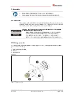
Danger of explosion through the use of couplings which are not suitable
for use in potentially explosive areas!
-
Only couplings may be used which are approved for use in potentially
explosive areas and which meet the requirements of the defined
characteristics, see the chapter “Technical data”, as from page 17.
-
Adhere to the assembly and operating instructions of the manufacturer.
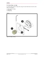
5.1.1 Flange-assembly
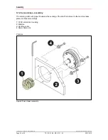
The centring collar with proper fit assures the centring of the shaft. Attachment to the machine takes
place via bolts in the flange.
1: ATEX-conformant coupling
2: Machine
3: Centring collar
Principle
Figure 1: Flange-assembly

