User's Manual l MB-COME6-4 UM 0100 l © 2022, TQ-Systems GmbH
Page 18
3.5.17
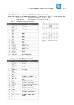
Debug LEDs
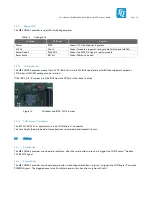
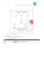
The MB-COME6-4 provides several LEDs for debug purposes.
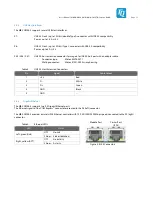
Table 13:
Debug LEDs
Function
PCB Text
Remark
Power
PWR
Green if 12 V input power is present
SUS S3
S3 act.
Green if module is in power-saving mode S3 (Suspend to RAM)
Power Good #
PWR GD#
Green if no PWR_OK signal is sent to module
Reset active
RST act.
Green if Reset is asserted
3.5.18
SPI Flash Socket
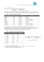
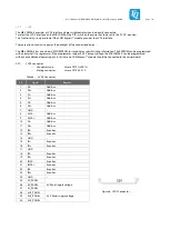
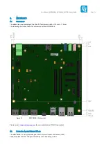
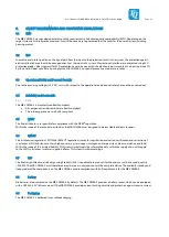
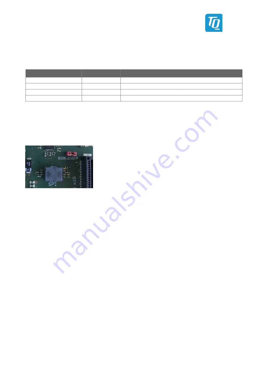
The MB-COME6-4 provides a socket for 3.3 V SPI flash. This is useful if a BIOS update fails or for BIOS development purposes.
SPI-Flashes with SO8W package can be inserted.
If the “BIOS_DIS1#” jumper is set, the BIOS from the SPI flash in the socket is active.
Figure 13:
SPI socket and BIOS_DIS1# Jumper
3.5.19
COM Express™ Connector
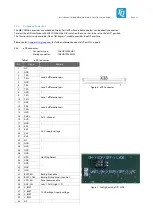
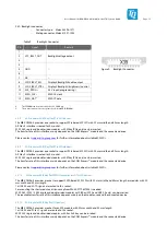
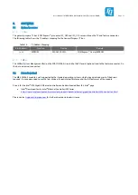
The EPT 401-55103-51 or equivalent is used as COM Express™ connector.
The stack height (board to board distance between carrier board and module) is 8 mm.
3.6
Buttons
3.6.1
Reset Button
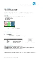
The MB-COME6-4 provides an on board reset button, when the reset button is pressed, it triggers the COM Express™ module
SYS_RESET# signal.
3.6.2
Power Button
The MB-COME6-4 provides an on board power button, when the power button is pressed, it triggers the COM Express™ module
PWRBTN# signal. The triggered event usually initiates a power state transition (e.g. from S0 to S5).

