User's Manual l MB-COME6-4 UM 0100 l © 2022, TQ-Systems GmbH
Page 15
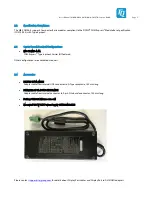
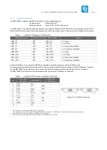
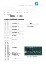
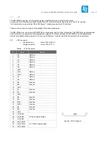
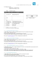
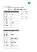
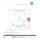
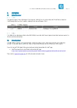
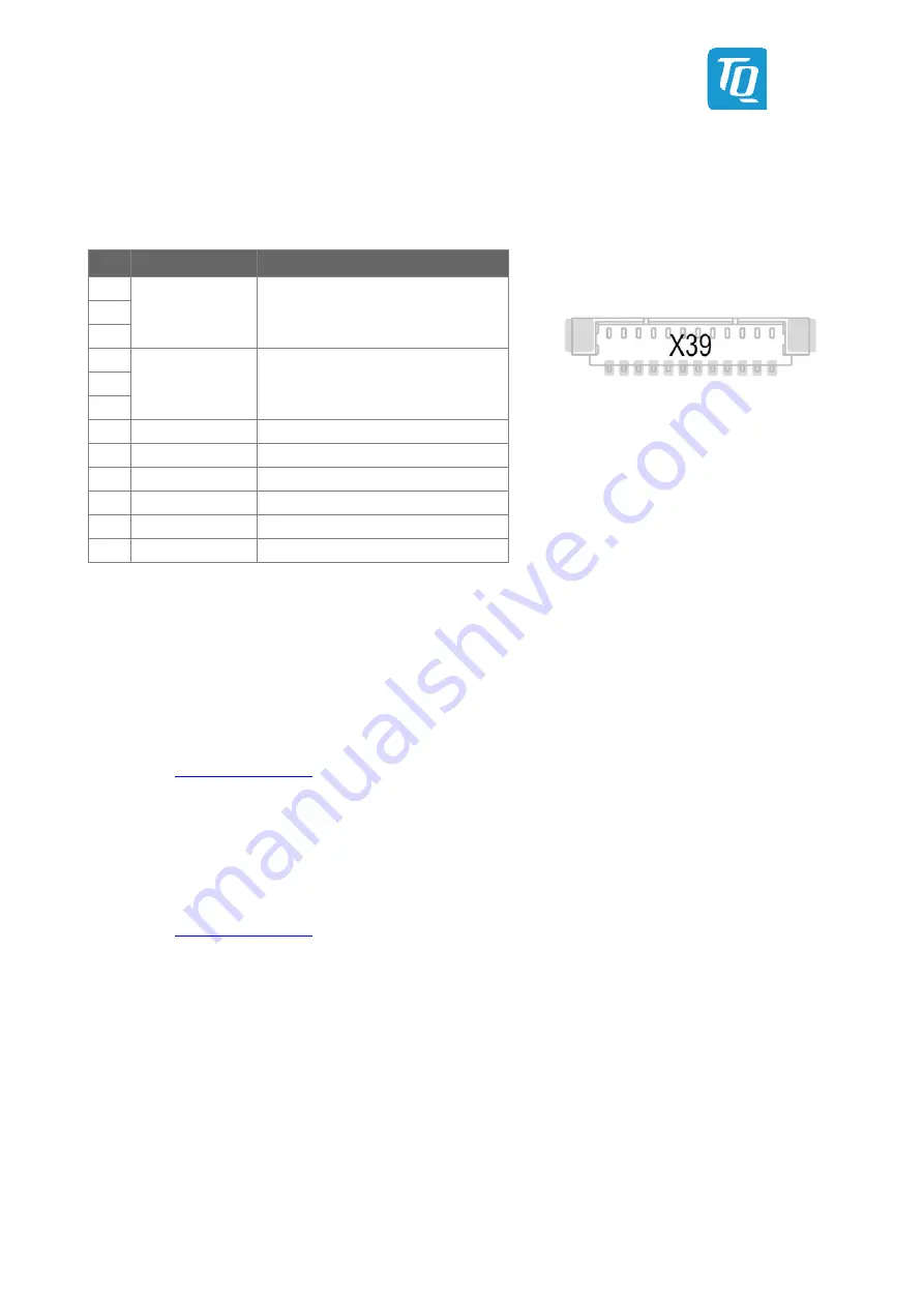
X39: Backlight connector,
−
Connector type: Molex 53398-1271
−
Mating connector: Molex 51021-1200
Table 9:
Backlight Connector
Figure 9: Backlight Connector
4:
The EEPROM can be powered by the 3V3_PROG pin.
5:
These pins can be used to program the on-board EDID EEPROM.
3.5.8
M.2 socket with M Key (for PCIe SSD devices)
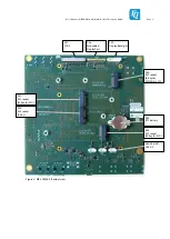
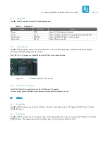
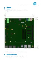
The MB-COME6-4 provides one socket to support PCIe based M.2 SSD with 22 mm width and 80 mm length.
A PCIe ×4 interface is routed to this socket.
M.2 2280 single and double sided modules with M key (PCIe only) can be inserted.
The transfer rate of this interface mainly depends on the COM Express™ module and the connected device.
Please contact
for further information about suitable M.2 SSDs.
3.5.9
M.2 socket with M Key (for PCIe SSD devices)
The MB-COME6-4 provides one socket to support PCIe based M.2 SSD with 22 mm width and 42 mm length.
A PCIe ×2 interface is routed to this socket.
M.2 2242 single and double sided modules with M key (PCIe only) can be inserted.
The transfer rate of this interface mainly depends on the COM Express™ module and the connected device.
Please contact
for further information about suitable M.2 SSDs.
3.5.10
M.2 socket with B Key (for WWAN modules or SATA SSD devices)
The MB-COME6-4 provides a socket to support SATA based M.2 SSDs with 22 mm width and 80 mm length or modules with 22
mm width and 42 mm length.
1x USB 2.0 and SATA signals are routed to this socket.
For mounting the short module a distance cap from Würth 9779807025 is needed.
M.2 2280 / 2242 / 3042 single and double sided modules with B Key (SATA and USB 2.0 only) can be inserted.
The reachable transfer rate of this interface depends mainly on the module used and the connected device.
3.5.11
M.2 socket with E Key (for I/O devices)
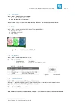
The MB-COME6-4 provides a socket for an M.2 module with 22 mm width and 30 mm length.
1x USB 2.0 and PCIe ×1 signals are routed to this socket.
M.2 2230 single and double sided modules with E or A+E key can be inserted.
The transfer rate of this interface mainly depends on the COM Express™ module and the connected device.
Pin
Signal
Remark
1
VCC_BKLT_OUT
Backlight voltage output
2
3
4
GND
–
5
6
7
NC
–
8
LCD0_BKLT_EN
Display 0 Backlight Enable output
9
LCD0_BKLT_CTRL
Display 0 Backlight (brightness) control
10
3V3_PROG
4
3.3 V input (programming)
11
EDID_CLK
5
EDID I
2
C clock
12
EDID_DAT
5
EDID I
2
C data


