


Preliminary User's Manual l TQMLS1028A UM 0001 l © 2019, TQ-Systems GmbH
Page 13
4.9
RTC
The RTC PCF85063ATL is supported by U-Boot and Linux kernel.
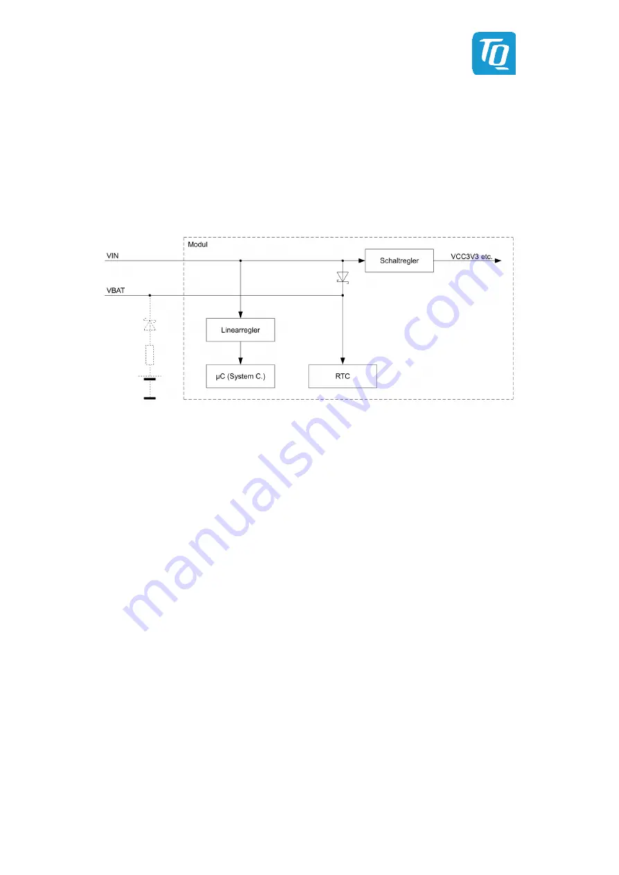
The RTC is powered via V
IN
, battery buffering is possible (battery on carrier board, see Illustration 10).
The alarm output INTA# is routed to the module connectors. A wake-up is possible via the system controller.
The RTC is connected to the I
2
C controller 1, device address is
The accuracy of the RTC is primarily determined by the characteristics of the quartz used. The type FC-135 used on the
TQMLS1028A has a standard frequency tolerance of ±20 ppm at +25 °C. (Parabolic coefficient: max. –0.04 × 10
–6
/ °C
2
)
This results in an accuracy of approximately 2.6 seconds / day = 16 minutes / year.
Illustration 10: Block diagram RTC buffering
4.10
Temperature monitoring
Due to the high power dissipation, temperature monitoring is absolutely necessary in order to comply with the specified
operating conditions and thus ensure reliable operation of the TQMLS1028A. The temperature critical components are:
•
CPU
•
DDR4 SDRAM
The following measuring points exist:
•
CPU temperature:
Measurement via diode integrated in CPU, read out via external channel of SA56004
•
DDR4 SDRAM:
Measurement by combined temperature sensor / EEPROM SE97B
•
VDD switching regulator:
SA56004 (internal channel) for measuring the VDD switching regulator
The open-drain Alarm Outputs (open drain) are connected together and have a pull-up to signal TEMP_OS#.
Control via I2C controller 1 of the CPU, device addresses see Table 9.
Further details can be found in the SA56004EDP data sheet (5).
An additional temperature sensor is integrated in the configuration EEPROM, see 4.8.2.
4.11
Supply
The TQMLS1028A requires a 5 V supply with a maximum tolerance ±5 %.


