


User's Manual l MBa8x UM 0100 l © 2021, TQ-Systems GmbH
Page 23
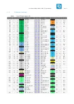
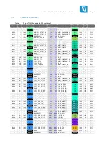
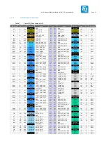
Table 10:
I
2
C devices, address mapping on TQMa8x and MBa8x
Bus
Device
Component
Address
Note
I2C1
TQMa8x
SE97BTP
0x1B
Temperature sensor
0x53
EEPROM Read/Write
0x33
EEPROM Protection Command
EEPROM 24LC64T
0x57
Optional
RTC PCF85063ATL
0x51
Optinol
TSE SE050
0x48
Optional
MBa8x
Mini-PCIe
NA
3.3 V
Audio-Codec
0x18
1.8 V
Clock driver
0x68
3.3 V
mikroBUS
NA
3.3 V
PCIe (M.2)
NA
3.3 V
Temperature sensor
0x1C
3.3 V
Temperature sensor
0x54
3.3 V
Temperature sensor
0x34
3.3 V
I2C2
MBa8x
-
-
Available on pin header; 1.8 V
PMIC_I2C TQMa8x
PMIC PF8x00 #1
0x08
1.8 V
PMIC PF8x00 #2
0x09
1.8 V
A sensor of type SE97BTP with integrated EEPROM is available on the MBa8x for monitoring the temperature. This sensor is also
installed on the TQMa8x. Both sensors are read out via I2C1. The address of the sensor on the MBa8x can be changed by
reassembling resistors. When changing the address, care must be taken to avoid address conflicts with existing I2C devices. The
placement options are documented in the latest circuit diagram.
I2C is provided at the microBUS interface of the MBa8x. The exact address depends on the used module and must always be
checked to avoid address conflicts.
I2C1 is connected to the PCIe M.2 connector with 0 Ω resistors. These also allow this connection to be disconnected if required.
The I2C address depends on the card used and must always be checked to avoid address conflicts.
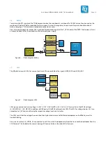
I2C1 is connected to the Mini PCIe connector with 0 Ω resistors. These also allow this connection to be disconnected if required.
The I2C address depends on the card used and must always be checked to avoid address conflicts.
The PCIe clock generator is connected I2C1 on 1.8 V level with 0 Ω resistors. These allow this connection to be disconnected if
required. The I2C address is fixed and set to 0x68.
If required, the USB 3.0 hub can also be connected to I2C1. The 0 Ω resistors required for this are not equipped! The exact address
is not fixed and can be adjusted by placing the bootstrap resistors. With this definition you have to pay attention to possible
address conflicts.
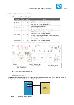
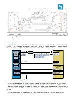
3.11
GPIO port expander
An 8-fold port expander PCA9538 is used to control various components on the MBa8x, see Table 11.
The port expander is controlled via I2C1. The address of the port expander can be altered by reassembling resistors.
When changing the address, care must be taken to avoid address conflicts with existing I
2
C devices, see
Fehler! Verweisquelle
konnte nicht gefunden werden.
.
The assembly options are documented in the schematic of the MBa8x.
In the initial state after switching on, all ports are set as input and the respective connected component is thus deactivated.
The I/O level of the signals is 1.8 V.


