14
Unmanaged/Easy Smart Rackmountable Switch
Connection
■
The device is correctly connected to other network devices.
3.4 Power On
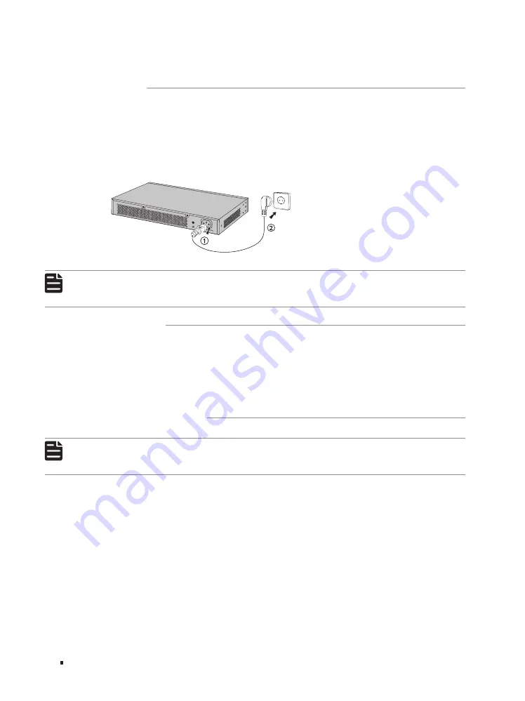
Plug the negative connector of the provided power cord into the power socket of the device and plug
the positive connector into a power outlet as the following figure shows.
Figure 3-3
Connecting to Power Supply
Note:
The figure is to illustrate the application and principle. The provided plug and the socket in
your region may differ from the figures above.
3.5 Initialization
After the device is powered on, it begins the Power-On Self-Test. A series of tests run automatically
to ensure the device functions properly. During this time, the LED indicators will respond as follows:
1. The PWR/Power LED indicator will light up.
2. The LED indicators of all the ports will flash momentarily and then turn off again after the
initialization.
3.6 Accessing the Switch
Note:
Only for TL-SG1016DE/TL-SG1024DE/TL-SG1016PE/TL-SG1218MPE, you can access and
manage the switch.
After the initialization finished, you can access and manage the switch using the Web-based GUI
(Graphical User Interface) or using the Configuration Utility.
Using the Web-Based GUI
To access and manage the switch using the Web-Based GUI, take the following steps:
1. Find the IP address of the switch.
■
By default, the switch receives an IP address from a DHCP server (or a router that functions as a
DHCP server) in your network. You can find this IP address on the DHCP server.
■
If the switch cannot receive an IP address from a DHCP server, it uses the static IP address of
192.168.0.1, with a subnet mask of 255.255.255.0.


