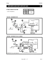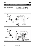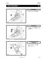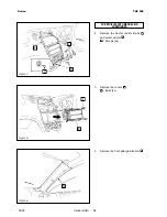
Celica (RHD) - 21
Celica
TNS 500
09-99
WIRE HARNESS
AND WIRE
HARNESS SUB-ASSEMBLY
INSTALLATION
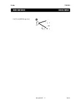
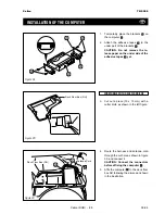
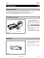
1.
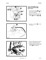
Route the wire harness
and the
wire harness sub-assembly
as
shown in the left figure.
2.
Secure the speed sensor wire (vio-
let/white) of the wire harness sub-
assembly
with the tape
(or
).
26
4
2
2
3
2
3
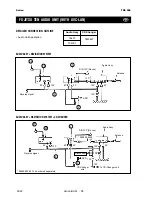
Figure 24
6
3
2
4
26
Tape
or
26
Tape
or
4
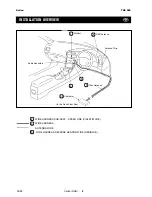
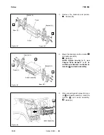
3.
Route the wire harness
as shown
the left figure.
3
Figure 25
3
;;;
;;;
;;;
;;;
;;;
;;;
yyy
yyy
yyy
yyy
yyy
yyy
;;;
;;;
;;;
;;;
;;;
;;;
yyy
yyy
yyy
yyy
yyy
yyy
;;
;;
;;
yy
yy
yy
;;;
;;;
;;;
yyy
yyy
yyy
;;
;;
yy
yy
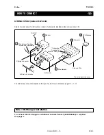
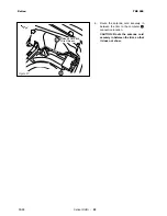
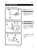
4.
Remove the floor carpet, and route the
antenna cord behind the rear seat.
5.
Adjust the length of the antenna cord,
and affix it after routing the cord to the
computer
procedures in (6).
20
Figure 26
3
26
Tape
or
4
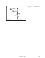
Antenna Cord
and Wire Harness

