


REMARKS
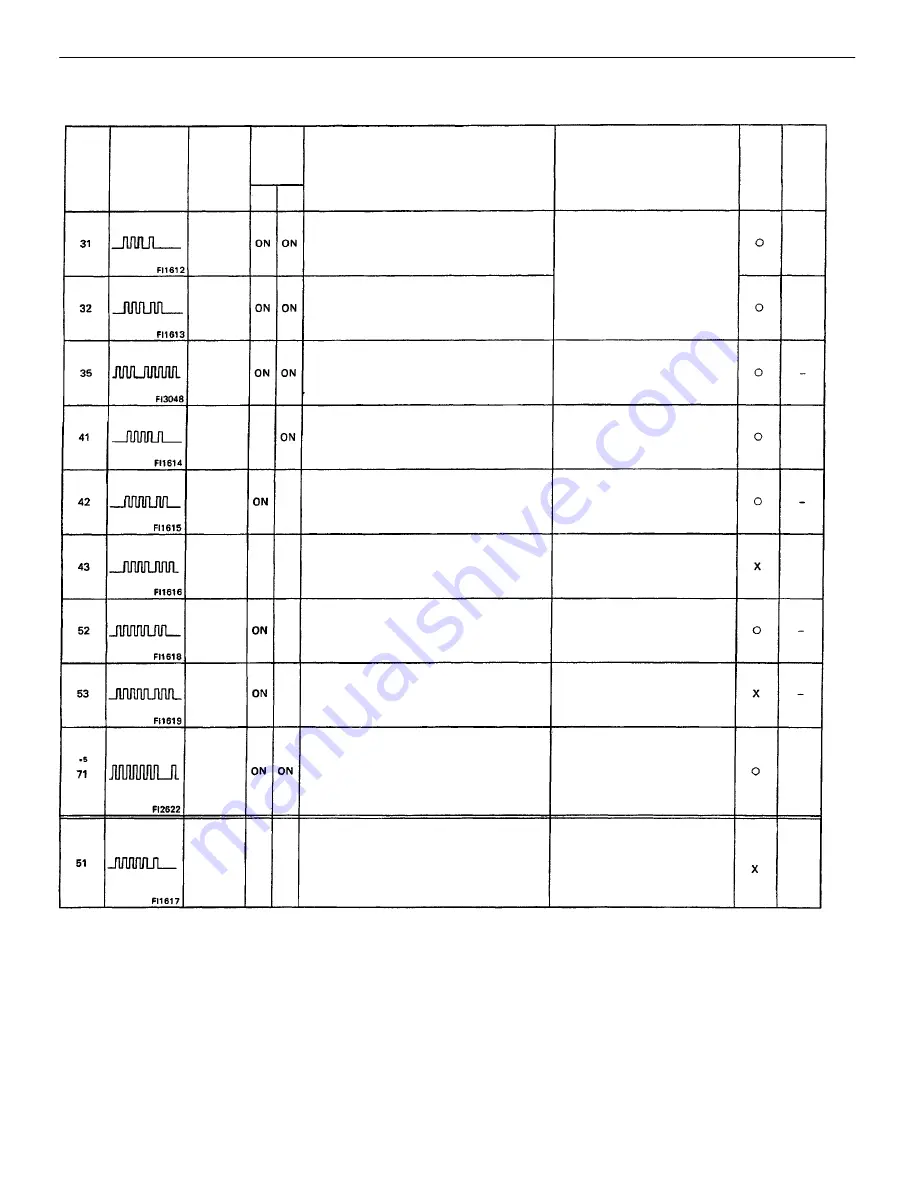
*1: ”ON’ displayed in the diagnosis mode column indicates that the malfunction indicator lamp is lighted up when a malfunction is detected. ”OFF”
indicates that
the ”CHECK” does not light up during malfunction diagnosis, even if a malfunction is detected. ”N.A.” indicates that the item is not included in
malfunction
diagnosis.
*2: ”O” in the memory column indicates that a diagnostic trouble code is recorded in the ECM memory when a malfunction occurs. ”X” indicates that a
diagnostic
trouble code is not recorded in the ECM memory even if a malfunction occurs. Accordingly, output of diagnostic results is performed with the IG SW
ON.
*3: The malfunction indicator lamp comes on if malfunction occurs only for California specifications,
*4: No. (2) in the diagnostic contents of codes No.25 and 26 apply to California and C&C specification vehicles only, while (1) applies to all models.
*5: Code 71 is used only for California specifications and C&C.
*6: “2 trip detection logic” (See page
*7: Except for California 2WD.
With the engine coolant temp. at 60
C (140
F)
or more, 240 seconds from start of EGR
operation.
The EGR gas temp. is less than 55
C ( 131
F)
and the EGR gas temp. has risen less than
20
C (36
C) during the 240 seconds.
*6 (2 trip detection logic)
•
Open in EGR gas temp. sen-
sor circuit
•
Open in VSV circuit for EG R
•
EGR vacuum hose discon-
nected, valve stuck
•
Clogged in EGR gas passage
•
ECM
At idling, open or short detected continuously
for 0.5 sec. or more in volume air flow meter
circuit.
•
Open – VC
•
Short – VC – E2
•
A/C switch circuit
•
Throttle position sensor 1 D L cir-
cuit
•
Park/Neutral position switch circuit
•
Accelerator pedal, cable
•
ECM
Open or short detected continuously for 0.5
sec: or more in volume air flow meter circuit.
•
Open – E2
•
short – VS – VC
DIAGNOSTIC TROUBLE CODES (Cont’d)
Open or short detected in throttle position
sensor
signal (VTA) for 0.5 sec. or more.
IDL contact is ON and VTA output exceeds
1.45 V.
SPD signal is not input to the ECM for at least
8 seconds during high load driving with engine
speed between 2,750 rpm and 4,000 rpm.
•
Open or short in starter signal
circuit
•
Open or short in IG SW or main
relay circuit
•
ECM
Displayed when A/C is ON, IDL contact OFF or
shift position in “R”, “D”, ”2”, or ”L” positions
with the DLC1 terminals E1 and TE1 connected.
Engine speed is between 650 rpm and 5,200
rpm
and engine control module (for knock control)
malfunction is detected.
With engine speed between 1,600 rpm – 5,200
rpm, signal from knock sensor is not
input to ECM for 6 revolution. (KNK)
Starter signal (STA) is not input to ECM even
once until engine reaches 800 rpm or more
when cranking.
•
open or short in volume air
flow
meter circuit
•
Volume air flow meter
•
ECM
•
Open or short in throttle posi-
tionsensor
circuit
•
Throttle position sensor
•
ECM
•
Open or short in vehicle speed
sensor circuit
•
Vehicle speed sensor
•
ECM
•
Open or short in knock sensor
circuit
•
Knock sensor (looseness, etc.)
•
ECM
Open or short detected in BARO sensor circuit
for 0.5 sec. or more.
Number of
blinks
Malfunction
Indicator
Lamp
*1
M aI–
function
Indicator
Lamp
6ARO
Sensor
Signal
(only
C&C)
Volume
Air Flow
Meter
Signal
Volume
Air Flow
Meter
Signal
Throttle
Position
Sensor
Signal
EGR
System
Mal–
function
Vehicle
Speed
Sensor
Signal
Switch
Condition
Signal
Knock
Control
signal
Knock
Sensor
Signal
Trouble Area
*2
Memory
Diagnosis
Starter
Signal
Code
No.
See
Page
System
•
ECM
•
ECM
*
3
ON
V02184
OFF
OFF
OFF
N.A.
N.A
.
N.A.
N.A.
Normal
Mode
Test
Mode
–
ENGINE
MFI SYSTEM
EG2–177
Содержание 22R-E
Страница 1: ...INTRODUCTION INTRODUCTION IN 1 ...
Страница 9: ...VEHICLE LIFT AND SUPPORT LOCATIONS INTRODUCTION VEHICLE LIFT AND SUPPORT LOCATIONS IN 9 ...
Страница 35: ...22R E ENGINE ENGINE EG1 1 ...
Страница 45: ...HINT Adjust idle mixture as necessary ENGINE ENGINE MECHANICAL EG1 11 ...
Страница 49: ...CYLINDER HEAD COMPONENTS ENGINE ENGINE MECHANICAL EG1 15 ...
Страница 80: ...CYLINDER BLOCK COMPONENTS ENGINE ENGINE MECHANICAL EG1 46 ...
Страница 110: ...EXHAUST SYSTEM COMPONENTS ENGINE ENGINE MECHANICAL EG1 76 ...
Страница 116: ...LAYOUT AND SCHEMATIC DRAWING Federal and Canada ENGINE EMISSION CONTROL SYSTEMS EG1 82 ...
Страница 117: ...LAYOUT AND SCHEMATIC DRAWING Calif ENGINE EMISSION CONTROL SYSTEMS EG1 83 ...
Страница 118: ...POSITIVE CRANKCASE VENTILATION PCV SYSTEM ENGINE EMISSION CONTROL SYSTEMS EG1 84 ...
Страница 122: ...EXHAUST GAS RECIRCULATION EGR SYSTEM Federal and Canada ENGINE EMISSION CONTROL SYSTEMS EG1 88 ...
Страница 126: ...EXHAUST GAS RECIRCULATION EGR SYSTEM Calif ENGINE EMISSION CONTROL SYSTEMS EG1 92 ...
Страница 135: ...MFI SYSTEM DESCRIPTION ENGINE MFI SYSTEM EG1 101 ...
Страница 211: ...FUEL PUMP ENGINE MFI SYSTEM EG1 177 ...
Страница 226: ...FUEL TANK AND LINE COMPONENTS ENGINE MFI SYSTEM EG1 192 ...
Страница 230: ...3 INSTALL INTAKE AIR CONNECTOR ENGINE MFI SYSTEM EG1 196 ...
Страница 239: ...2 INSTALL THROTTLE BODY See page EG1 202 ELECTRONIC PARTS LOCATION ENGINE MFI SYSTEM EG1 205 ...
Страница 278: ...3VZ E ENGINE ENGINE EG2 1 ...
Страница 299: ... ENGINE ENGINE MECHANICAL EG2 22 ...
Страница 300: ... ENGINE ENGINE MECHANICAL EG2 23 ...
Страница 326: ...CYLINDER HEAD COMPONENTS ENGINE ENGINE MECHANICAL EG2 49 ...
Страница 327: ... ENGINE ENGINE MECHANICAL EG2 50 ...
Страница 367: ...CYLINDER BLOCK COMPONENTS ENGINE ENGINE MECHANICAL EG2 90 ...
Страница 411: ...EXHAUST SYSTEM ENGINE ENGINE MECHANICAL EG2 134 ...
Страница 419: ...LAYOUT AND SCHEMATIC DRAWING ENGINE EMISSION CONTROL SYSTEMS EG2 142 ...
Страница 435: ...MFI SYSTEM SYSTEM CIRCUIT DESCRIPTION ENGINE MFI SYSTEM EG2 158 ...
Страница 476: ... ENGINE MFI SYSTEM EG2 199 ...
Страница 497: ...INJECTOR COMPONENTS FOR REMOVAL AND INSTALLATION ENGINE MFI SYSTEM EG2 220 ...
Страница 508: ...FUEL TANK AND LINE COMPONENTS ENGINE MFI SYSTEM EG2 231 ...
Страница 521: ...ELECTRONIC PARTS LOCATION ENGINE MFI SYSTEM EG2 244 ...
Страница 569: ...IGNITION SYSTEM IGNITION SYSTEM IG 1 ...
Страница 596: ...STARTING SYSTEM STARTING SYSTEM ST 1 ...
Страница 597: ...STARTER COMPONENTS STARTING SYSTEM Starter ST 2 ...
Страница 609: ...CHARGING SYSTEM CHARGING SYSTEM CH 1 ...
Страница 613: ...GENERATOR COMPONENTS CHARGING SYSTEM Generator CH 5 ...


