background image

READ THROUGH THIS MANUAL

BEFORE STARTING CONSTRUCTION.

IT CONTAINS IMPORTANT INSTRUCTIONS 

AND WARNINGS CONCERNING THE 

ASSEMBLY AND USE OF THIS MODEL.

WEIGHT

35 – 38 oz [992 –1077g]

WING LOADING

7.5 – 8.0 oz/ft

2

 [23 – 24 g/dm

2

]

RADIO

3-Channel, Two Standard Servos

or Two Mini Servos with

at least 35 g of torque.

To w e r 
Hobbies

®


guarantees 
this kit to be 
free from defects 
in both material and 
workmanship at the 
date of purchase. This 
warranty does not cover any 
component parts damaged by 
use or modification. In no case 
shall Tower Hobbies’ liability exceed 
the original cost of the purchased kit. 
Further, Tower Hobbies reserves the right to 
change or modify this warranty without notice.
In that Tower Hobbies has no control over the final 
assembly or material used for final assembly, no 
liability shall be assumed nor accepted for any damage 
resulting from the use by the user of the final 
user-assembled product. By the act of using the 
user-assembled product, the user accepts all resulting liability.
If the buyer is not prepared to accept the liability associated with the 
use of this product, the buyer is advised to return this kit immediately in 
new and unused condition to the place of purchase.
To make a warranty claim send the defective part or item to Hobby Services at 
the address below:
Hobby Services • 3002 N. Apollo Dr.  Suite 1 • Champaign IL  61822 • USA
Include a letter stating your name, return shipping address, as much contact information 
as possible (daytime telephone number, fax number, e-mail address), a detailed description 
of the problem and a photocopy of the purchase receipt. Upon receipt of the package the 
problem will be evaluated as quickly as possible.

WA

R

R

A

N

T

Y

TOWA4020

© 

2014 Tower Hobbies.

®

  A subsidiary of Hobbico, Inc. 

®

®

TOWER HOBBIES

Champaign, Illinois

 (217) 398-8970 ext. 5

WINGSPAN

78.5 in [1995mm]

WING AREA

678 sq in [43.7 dm

2

]

LENGTH

41 in [1040 mm]

[email protected]

I N S T R U C T I O N   M A N U A L

MOTOR

Included

Содержание VistaBL

Страница 1: ... user of the final user assembled product By the act of using the user assembled product the user accepts all resulting liability If the buyer is not prepared to accept the liability associated with the use of this product the buyer is advised to return this kit immediately in new and unused condition to the place of purchase To make a warranty claim send the defective part or item to Hobby Servic...

Страница 2: ...d air shows Failure to comply with the Safety Code excerpts printed in the back of the manual may endanger insurance coverage Additionally training programs and instructors are available at AMA club sites to help you get started the right way There are over 2 500 AMA chartered clubs across the country Contact the AMA at the address or toll free phone number that follows Academy of Model Aeronautic...

Страница 3: ... less depending on the condition of your batteries and manufacturer s specified charge rate The Onyx can also charge larger batteries and batteries other than LiPo so it is a versatile charger you can grow into The 235 also has and LCD digital display screen so you can see how much capacity it took to recharge the battery required for monitoring the condition of your batteries and calculating how ...

Страница 4: ...Product Support by e mail at productsupport hobbico com or by telephone at 217 398 8970 Order No Description REPLACEMENT PARTS LIST Fuselage Wing Tail Surfaces Motor Folding Prop Assembly Folding Blade Set Decals ESC 30A TOWA4021 TOWA4022 TOWA4023 TOWA4024 TOWA4025 TOWA4026 TOWA4027 TOWA4028 CONTENTS 1 Fuselage 2 Left Wing 3 Right Wing 4 Horizontal Stabilizer 5 Vertical Stabilizer 6 Fin Braces 7 S...

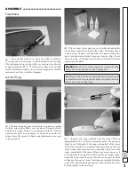
Страница 5: ...epoxy brush paper towels and denatured alcohol for epoxy clean up Hint To cut down on waste cut the paper towels into several small squares as shown in the photo Caution Do not use 5 minute epoxy for joining the wing halves It will not provide enough working time Read steps 3 and 4 all the way through before proceeding It is important to use the proper technique for joining the wing halves to ensu...

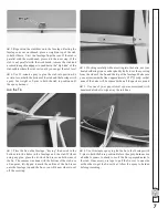
Страница 6: ...sh ASSEMBLE THE FUSELAGE Join the Stabilizer 1 Cut off any covering that has been wrapped around the side of the fuselage over the top of the stab saddle where the stabilizer goes 2 Place the stab on the fuselage keying the notches in the stab into the pegs on the fuselage Use a fine point felt tip pen to mark the outline of the fuselage onto the stab 3 Take the stab off the fuselage and follow th...

Страница 7: ...ri stock fin braces on both sides of the fin The same as was done with the bottom of the stab use a fine point felt tip pen to mark the outline of the fin braces onto the fuselage top and the fin so you will know where to cut off the covering 2 Working carefully without cutting into the balsa use your heated soldering iron or a sharp hobby knife to cut the covering from the sides of the fin and th...

Страница 8: ...orward rail as far forward as it will go and glue it into place but do not glue in the aft rail until instructed to do so Hook Up the Controls 1 Connect the clevis to the third hole out from the bottom of the elevator horn Note If the silicone retainer on the elevator clevis rubs against the inside of the fuselage sides use a hobby knife to trim the inside of the fuselage as necessary for free smo...

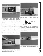
Страница 9: ... mm holes through the rails for the servo mounting screws Mount the servo with the screws that came with it 6 Move the rudder servo all the way over to the elevator servo Drill 1 16 1 6mm holes through the rails and mount the rudder servo with the screws that came with it 7 Center the servo arms as shown holding the elevator pushrod so the elevator is centered Mark the pushrod where it crosses the...

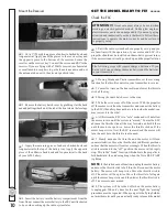
Страница 10: ...e the motor battery and the batteries in your transmitter 2 If using Futaba and Tactic transmitters set the reversing function for the throttle control in your transmitter to reverse 3 Center the trims on the transmitter and lower the throttle stick all the way 4 Swing the radio hatch cover to the side 5 Take the servo arms off of the servos With the propeller off the motor switch on the transmitt...

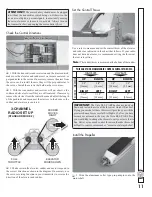
Страница 11: ...and motor respond in the correct direction as shown in the diagram If necessary use the servo reversing function in your transmitter to reverse the direction of the elevator and rudder Set the Control Throws Use a ruler to measure and set the control throw of the elevator and rudder as indicated in the chart that follows If your radio does not have dual rates we recommend setting the throws at the...

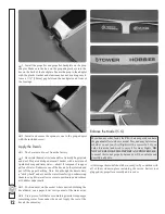
Страница 12: ...the decals have a sticky back and are not the water transfer type submersing them in soap water allows accurate positioning and reduces air bubbles underneath 3 Position decal on the model where desired Holding the decal down use a paper towel to wipe most of the water away 4 Use a piece of soft balsa or something similar to squeegee remaining water from under the decal Apply the rest of the decal...

Страница 13: ... under the tail or inside the fuselage behind the motor 5 IMPORTANT If you found it necessary to add any weight recheck the C G after the weight has been installed PREFLIGHT Identify Your Model No matter if you fly at an AMA sanctioned R C club site or if you fly somewhere on your own you should always have your name address telephone number and AMA number on or inside your model It is required at...

Страница 14: ...by the safety rules for the flying site I use and I will not willfully and deliberately fly my models in a careless reckless and or dangerous manner 5 I will not fly my model unless it is identified with my name and address or AMA number on or in the model Note This does not apply to models while being flown indoors 7 I will not operate models with pyrotechnics any device that explodes burns or pr...

Страница 15: ...ould be considerable resistance If the wing can be forced from the fuselage without having to strain your hands then there are probably not enough rubber bands IMPORTANT Flying a model with too few rubber bands can be dangerous The wing could actually detach from the fuselage resulting in a crash If the model exhibits any tendencies that indicate there are not enough rubber bands immediately land ...

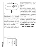
Страница 16: ...th the batteries This will prevent the downwind auto motor cutoff over the end of the flying field Landing Align the plane with the landing zone and always land into the wind Increase or decrease motor power as necessary to maintain your descent When the model is a foot or two 5m from the ground increasingly apply up elevator to slow the model without allowing it to climb Skim the ground until fly...

Отзывы: