


Chapter 2 — Getting Started
Installing the Customer Display for Lite type
Follow
the
procedures
below
to
install
the
Customer
Display.
1.
Connect
the
VFD
DB
9
cable
to
the
connector
as
shown.
2.
Replace
the
base
cover
and
affix
it
with
two
M3
screws.
3.
Attach
the
Customer
Display
to
the
base
of
the
FS100
Terminal
with
two
M3
screws.
4.
Lock
the
Customer
Display
to
the
customer
display
pole
bracket
with
two
M3
screws.
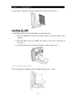
Installing the Customer Display for Pro type
Follow
the
procedures
below
to
install
the
Customer
Display.
1.
Plug
the
VFD
RJ
‐
45
connector
of
the
Customer
Display
into
the
COM5
port.
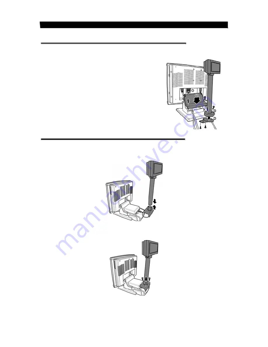
2.
Install
the
Customer
Display
and
the
cover
stand
in
place
with
three
M3
screws.
10


