background image

5

ENGLISH

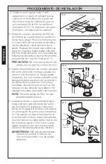
6)   The supply stop should be installed per 

the supply stop instruction at the location 
shown in the Before Installation section. 

hose to supply stop.


CAUTION:

 Hand-tighten only.

      Open the supply stop, checking for leak-

age. Slightly re-tighten if necessary. The 
water supply pressure should be 20 to 80 
psi static.

7)   

NOTE: 

are needed. The water will automatically 
stop at proper level.


-

per valve for proper operation.  Make sure 

in its proper position.

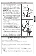
8)   Install the toilet tank lid onto the toilet tank 

top.

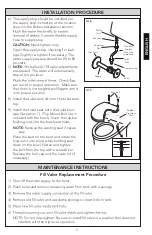
9)   Install the toilet seat onto the toilet bowl 

(see Illustration 7).  (Top Mount Bolt Set is 
included with the bowl).  Insert the rubber 
bushing nuts into the bowl seat holes.  


 NO TE:

 Remove the existing seat if neces-

sary.

      Place the seat on the bowl and rotate the 

hinge unit into place while holding seat 
down on the bowl. Fasten and tighten 
the bolt from the top with a screwdriver.  
Replace the bolt cap and the lower lid (if 
necessary).

Seat Bolt

Rubber

Brushing 

Nut

Ill. 7

MAINTENANCE INSTRUCTIONS

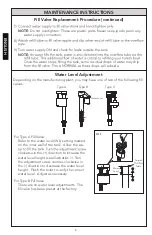
Fill Valve Replacement Procedure

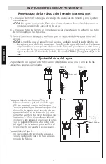
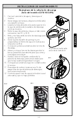
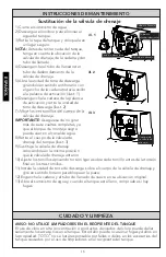
1)  Shut off the water supply to the toilet.

2)  Flush toilet and remove remaining water from tank with a sponge.

     NO 

 position that does not 

interfere with the trip lever operation.


Ill. 6

Water 

Inlet

Washer

Coupling 

Nut

Trim Plate

Flexible 

Supply 

Hose (not 

supplied)

Valve

Nut

Compression

Valve

Nipple

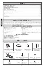
INSTALLATION PROCEDURE

Содержание MS614114CEFG

Страница 1: ...ge please con tact TOTO U S A Inc Customer Service Department 1155 Southern Road Morrow GA 30260 888 295 8134 or 678 466 1300 when calling from outside of U S A Installation Manual Manual de Instrucciones Manuel D Installation MS614114CEF G MS614114CUF G MS624124CEF G MS624234CEF G MS626124CEF G MS626234CEF G MS644114CEF G MS874114S G MS884114 MS904114 MS934214 E S F MS934304 E S F MS964214C E F G...

Страница 2: ...h In Dimensions 26 Replacement Parts 27 Check to make sure you have all these parts from the package COMMON TOOLS NEEDED INCLUDED PARTS 12 pipe wrench 10 adjustable wrench Carpenter s Level Tape Measure Plier MATERIALS REQUIRED Flexible Supply Tube Connector Supply Stop Valve Mounting T Bolts Nuts 2pc Wax Ring Seal Screwdriver Putty Knife Drill 11 64 5 16 drill bit for concrete tile installation I...

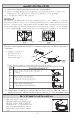
Страница 3: ...06W 12 Supplied 10 TSU01W 10R TSU03W 10R Optional Must be purchased separately 14 TSU01W 14R TSU03W 14R Optional Must be purchased separately 9 7 11 Please make sure that you have the correct outlet connection part 2 The water supply must be approximately 8 inches or 10 inches to the left facing the 1 Clean any debris out of the closet see Illustration 1 The bolt should be inserted into the slot w...

Страница 4: ...ional turn Secure the back side of the outlet connection to ers Insert the T bolts into the slots with the head down and threaded shank pointed upward NOTE Level the PVC outlet Do not use excessive force 5 Lift the toilet and gently lower it into lustration 5 Make sure that the spigot outlet of toilet slips into the rubber sleeve and that the T bolts fit through the openings in the base of toilet ...

Страница 5: ...7 Top Mount Bolt Set is included with the bowl Insert the rubber bushing nuts into the bowl seat holes NOTE Remove the existing seat if neces sary Place the seat on the bowl and rotate the hinge unit into place while holding seat down on the bowl Fasten and tighten the bolt from the top with a screwdriver Replace the bolt cap and the lower lid if necessary Seat Bolt Rubber Brushing Nut Ill 7 MAINT...

Страница 6: ...rection to decrease the water level height Flush the toilet to verify the correct water level Adjust as necessary For Type B Fill Valve There are no water level adjustments The fill valve has been preset at the factory Top of Tube Water Level Ill 1 Fill Valve Replacement Procedure continued NOTE Do not overtighten These are plastic parts Never use pipe dope on any water supply connection 8 pipe 9 ...

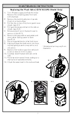
Страница 7: ...move it see Ill 3 6 Remove the grey rubber seal gasket and rinse under running water to clean see Ill 4 7 Place the gasket back on the ush tower 8 Align and place the ush tower into hous ing and gently press to snap and to lock into place 9 Replace the trip lever gear box and push down on lever to lock it in place 10 Carefully install the tank lid back on the tank 11 Flush the toilet several times...

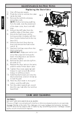
Страница 8: ...place the drain valve in the same position as the former drain valve 10 Tighten the screws applying light torque on each screw before final torque on all three screws 11 drain valve body and turn clockwise to lock the part 12 Hook the chain back to its original loction and the refill tube 13 Turn the water supply back on and check for any leak after the tank has been filled Flush Tower Drain Valve...

Страница 9: ... www totousa com Product registration is completely voluntary and failure to register will not dimin ish your limited warranty rights 5 THIS WARRANTY GIVES YOU SPECIFIC LEGAL RIGHTS YOU MAY HAVE OTHER RIGHTS WHICH VARY FROM STATE TO STATE PROVINCE TO PROVINCE OR COUNTRY TO COUN TRY 6 To obtain warranty repair service under this warranty you must take the Product or deliver it prepaid to a TOTO ser...

Страница 10: ...ese de que tiene todas las piezas del empaque Llave para Tubería de 12 Llave Adjustable de 10 Nivel de Carpintero Cinta para Medir Pinzas Destornillador MATERIALES NECESARIOS Tubo Abastecedor Conector Tope de Suministro Pernos de Montaje Cantidad 2 Sello Anillo de Cera Espátula para Masilla Taladro Broca de11 64 para Instalación en Piso de Madrea Broca de 5 16 para Instalación del Concreto Azulejo...

Страница 11: ...úrese de tener la parte de conexión de salida correcta 2 El suministro de agua debe estar a aproximadamente 8 ó 10 pulgadas mirando de frente al recipiente desde la línea del centro de la brida del suelo y 4 pulga das por encima del piso 1 Limpie la suciedad de la brida del suelo luego instale los pernos de montaje en las ranuras de la brida ver Ilustración 1 El perno debe insertarse en la ranura ...

Страница 12: ...e la parte posterior de la conexión de salida al piso utilizando 4 tornillos y arandelas Inserte los pernos en T en las ranuras con las cabezas hacia abajo y los vástagos roscados apuntando hacia arriba NOTA Nivele la salida de PVC No em plee demasiada duerza 5 Levante el inodoro y suavemente bájelo hasta colocarlo sobre la brida del suelo ver Ilustración 5 Asegúrese de que la salida de la espig d...

Страница 13: ...las tuercas revestidas de goma en los orificios del asiento del recipiente NOTA retire el asiento existente si fuera necesa rio Coloque el asiento sobre el recipiente y gire la unidad de charnelas hasta alcanzar la ubicación correcta mientras sostiene el asiento contra el recipiente Ajuste los pernos desde la parte superior con el destornillador Vuelva a colocar la tapa del perno y baje la tapa si...

Страница 14: ...a Dependiendo de la planta de fabricación usted debe tener una o ambas de las siguientes válvulas de llenado Tipo A Tipo B Water Level Para una Válvula de Llenado Tipo A Refere a la marca para el nivel de agua WL en la pared interior del tanque Permita que el agua llene el tanque Gire el tornillo de ajuste en el sentido de las agujas del reloj en la dirección para aumentar la altura del nivel del ...

Страница 15: ...a bajo el chorro de agua corriente para limpiarla ver Ill 4 7 Coloque la junta nuevamente sobre la torre de descarga 8 Alinee y coloque la torre de descarga sobre la base y presiónela suavemente para que entre y se asegure en su lugar 9 Vuelva a colocar la caja de cambios de la palanca de descarga y presione la traba para que la caja quede asegurada en su lugar 10 Coloque nuevamente la tapa con cu...

Страница 16: ...ustituya la válvula de drenaje colocándola en la misma posición que la válvula de drenaje anterior 10 Ajuste los tornillos aplicando torsión ligera sobre cada tornillo antes de la torsión final en los tres tornillos 11 Instale la unidad de torre de descarga sobre el cuerpo de la válvula de drenaje y gire en sentido horario para bloquear la pieza 12 Enganche la cadena y el tubo de llenado de nuevo ...

Страница 17: ...PECÍFICOS USTED PODRÍATENER OTROS DERECHOS QUE PUEDEN VARIAR DEPENDIENDO DEL ESTADO O PROVINCIA EN EL QUE SE ENCUENTRE 6 Para obtener el servicio de reparación de esta garantía debe llevar el Producto o enviarlo prep agado a un modulo de servicios TOTO junto con la prueba de compra recibo de compra original y una carta en la que plantee el problema o póngase en contacto con un distribuidor TOTO o ...

Страница 18: ... vous que vous avez toutes ces parties de l emballage PIÈCES INCLUSES Clé à Tube de 12 po Clé à Molette de 10 po Niveau à Bulle d Air Mètre à Ruban Pince MATERIEL REQUIS Tuyau d alimentaion Raccord Robinet d Arrêt Boulons de Montage 2 Rondelle en Caoutchouc Joint Tournevis Couteau à Mastiquer Perceuse Foret de 11 64 pour Installation sur Parquet Foret de 5 16 pour Installation sur sol en Béton Car...

Страница 19: ...tation en eau doit se situer à environ 8 po ou 10 po face à la cuvette depuis la ligne centrale de la bride de sol et à environ 4 1 2 po au dessus du sol 1 Nettoyez la bride de sol puis installez les boulons de montage Illustration 1 Les boulons doivent être insérés dans la fente tête en haut Ill 1 AVANT L INSTALLATION IMPORTANT En raison de la performance de nos puissants cyclones G Max E Max et ...

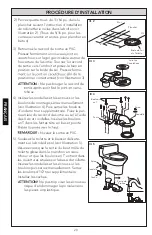
Страница 20: ...s d un demi tour supplémentaire Fixez la par tie arrière du raccord de sortie au sol à l aide des 4 vis et rondelles Insérez les boulons en T dans les fentes tête en bas et pointe Nivelez la sortie en PVC 5 Soulevez la toilette et la baisser délicate ment sur la bride de sol voir Illustration 5 Assurez vous que la sortie du bout mâle du toilette glisse dans le manchon en caou tchouc et que les bou...

Страница 21: ...tchouc dans les orifices du siège de la cuvette des toillettes Retirez la lunette existante si nécessaire Placez la lunette sur la cuvette et faire tourner la charnière pour la positionner tout en main tenant la lunette sur la cuvette Fixez et vissez le boulon par le dessus à l aide d un tournevis Remplacer le cache boulon et le couvercle inférieur si nécessaire Boulons de la Lunette Ecrou de la B...

Страница 22: ...d eau Suivant l usine de fabrication vous pouvez disposer de l un ou deux robinets de rem plissage suivants Type A Type B Water Level Pour le Valve de Remplissage de Type A C Reportez vous au niveau de l eau WL contexte marqué sur la paroi intérieure du réservoir Laisser l eau pour remplir le réservoir Tournez la vis de réglage dans le sens des aiguilles d une montre dans la direction pour augment...

Страница 23: ...té en caoutchouc et rincez à l eau courante pour nettoyer voir Ill 4 7 Replacez le joint d étanchéité sur la colonne de la chasse d eau 8 Alignez la colonne de la chasse d eau et placez la dans le boîtier puis appuyez dessus légèrement pour la bloquer et la verrouiller en place 9 Replacez la boîte d engrenages du levier de déclenchement et appuyez sur la barrette pour la verrouiller en place 10 Re...

Страница 24: ...lve du drain dans la même position que l ancienne valve du drain 10 Serrez les vis en exerçant un serrage léger sur chaque vis avant le serrage 11 Installez l unité de la chasse d eau sur le corps de la valve du drain et tournez dans le sens horaire pour attacher la pièce 12 Accrochez la chaîne et remplissez le tube à son niveau d origine 13 Ouvrez l arrivée en eau et lorsque le fuites ill 1 ill 2...

Страница 25: ...5 CETTE GARANTIE DONNE DES DROITS SPÉCIFIQUES IL EST POSSIBLE QUE L ACHETEUR AIT D AUTRES DROITS QUI VARIENT DUN ÉTAT A UN AUTRE OU D UNE PROVINCE À L AUTRE 6 Pour obtenir une réparation selon les termes de cette garantie l acheteur doit livrer à un centre de réparation de TOTO port payé avec preuve d achat reçu de caisse original et une lettre expliquant le problème ou contacter un distributeur d...

Страница 26: ... MS626214CEF G 28 7 16 16 1 8 28 1 2 16 3 16 MS644114CEF G 28 3 4 16 1 8 25 5 8 16 1 2 MS874114S G 28 15 27 1 2 16 1 2 MS884114 28 15 23 3 4 16 1 2 MS904114 29 1 2 15 23 1 2 21 1 4 MS934214 S E F 28 1 8 16 1 8 27 1 2 18 5 8 MS934304 S E F 28 1 8 16 1 8 27 1 2 18 5 8 MS964214C E F G 28 1 8 16 1 8 27 3 4 17 3 4 MS974224C E F G 28 1 4 16 1 8 28 18 MS984244CF G 28 16 1 8 26 1 4 20 1 2 NOTE Consult you...

Страница 27: ...cement Parts for Flapper Type Drain Valve Replacement Parts for Tower Type Drain Valve Flapper Tapón Clapet THU499S THU499S 9BU094 THU499S THU499S THU499S THU499S THU499S THU499S THU499S N A Model Modelo Modèle CST614CEF G T CST624CEF G T CST626CEF G T CST644CEF G T CST934EFT CST964CEF G T CST974CEF G T Drain Valve Válvula de drenaje Valve du drain THU451 10A A THU451 10A A THU451 10A A THU460 6D ...

Страница 28: ...quiry For product warranty registration TOTO U S A Inc recommends online warranty registration Please visit our web site http www totousa com If you have questions regarding warranty policy or coverage please con tact TOTO U S A Inc Customer Service Department 1155 Southern Road Morrow GA 30260 888 295 8134 or 678 466 1300 when calling from outside of U S A ...

Отзывы: