


12
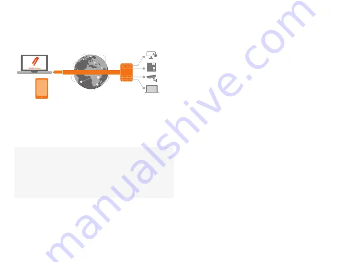
With its factory default settings, the Node is connected to
the Internet via its WAN port or a USB modem which can
be connected to the USB port of the Node. In this mode,
the Node creates its own protected local network for the
connected devices. In this configuration, only devices that
are connected to the Node by cable or via WLAN access
point are accessible with the Key.
Note:
•
See “USB Modem settings for the Node” (page 18) to
connect a USB modem to the Node´s USB port.
•
If the Node is connected to a DHCP enabled network via
any of its LAN ports (LAN1, LAN2 or LAN3) the Lock’s own
LAN functionality can be restored by resolving any DHCP
conflicts by removing improper LAN connections to the
Node.
CONNECTING NETWORK DEVICES TO THE NODE
A) Connecting device(s) that use dynamic IP addresses
(DHCP)
Devices with a DHCP client enabled will automatically
connect to the Node. Plug the device(s) into the Lock’s LAN
port(s) and go!
B) Connecting device(s) with Fixed IP addresses by
4.1.1 DEPLOYING NODE IN “LOCK MODE”
configuring the DEVICE to the NODE:
1. Before connecting device to Node, connect to device per
device manufacturer’s instructions on your PC and assign a
new static IP address to device(s) from the Node´s IP range
printed on the bottom label of the Node. Do not add same
IP address. We recommend adding the next IP sequential
address ABOVE the IP address on the Node, and so forth
for each additional device. (*Note: Node´s IP and netmask
address can also be found in the service port at Network >
LAN)
2.
Plug the device(s) into the Node´s LAN port(s) and go!
C) Connecting device(s) with Fixed IP addresses by
configuring the NODE to the DEVICE:
1.
Get the device(s’) IP address(es) and netmask.
2. Connect your PC to the Node´s service port and log in
following the step 1 on page 17 “Updating the Node
software”.
3.
Go to Network->LAN and change the IP address in the
“IPv4 address” field to the next IP address above the IP
address of the device (step 1). Also check that the “IPv4
netmask” field corresponds to the netmask set on the
device and change it if necessary.
4.
Plug the device(s) into the Node´s LAN port(s) and go!
5. ADVANCED/ENTERPRISE USERS ONLY: Go to
Network>LAN DHCP SERVER and set the “Start” value so
that it’s higher than all used static addresses. Set the limit
value to a suitable value so that it covers the rest of the
unused addresses in the LAN range. For example, the range
192.168.5.50 – 192.168.5.254 contains 205 addresses so
the “Start” value would be 50 and the “Limit”value would
be 205.
4. TOSIBOX
®
LOCK INSTRUCTIONS
VPN tunnel through Internet
TOSIBOX
®
Mobile
Client
TOSIBOX
®
Key
Firewall
TOSIBOX
®
Lock
HMI
PLC
Camera
PC


