


– 37 –
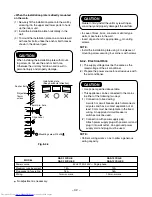
CAUTION
Installation in the following places may result in
trouble. Do not install the unit in such places.
• A place full of machine oil.
• A saline place such as coast.
• A place full of sulfide gas.
• A place where high-frequency waves are likely
to be generated as from radio equipment,
welders, and medical equipment.
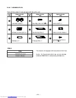
8-5-1. Required Tools for Installation Work
1) Philips screw driver
2) Hole core drill (65mm)
3) Gaugramanifold
4) Spanner
5) Pipe cutter
6) Knife
7) Reamer
8) Gas leak detector
9) Tape measure
10) Thermometer
11) Mega-tester
12) Electro circuit tester
13) Vacuum pump
14) Hexagonal wrench (5mm)
15) Torque wrench
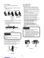
8-5-2. Refrigerant Piping Connection
<Flaring>
(1) Cut the pipe with a pipe cutter.
90˚
Obliquity
Roughness
Warp
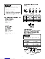
Half union or packed valve
Flare nut
Externally
threaded
side
Internally
threaded
side
Use a wrench
to secure.
Use a torque wrench
to tighten.
Fig. 8-5-4
Fig. 8-5-2
(2) Insert a flare nut into the pipe, and flare the pipe.
Outer
dia.
6,35mm
9,52mm
12,7mm
A (mm) R22
Imperial
Rigid
1,0 ~ 1,5
0,5 ~ 1,0
1,0 ~ 1,5
0,5 ~ 1,0
1,5 ~ 2,0
0,5 ~ 1,1
A (mm) R410A
Imperial
Rigid
1,5 ~ 2,0
1,0 ~ 1,5
1,5 ~ 2,0
1,0 ~ 1,5
Die
Pipe
A
Fig. 8-5-3
<Tightening connection>
Align the centers of the connecting pipes and tighten
the flare nut as far as possible with your fingers.
Then tighten the nut with a spanner and torque
wrench as shown in the figure.
CAUTION
• Do not apply excess torque. Otherwise, the
nut may crack depending on the installation
conditions.
Outer dia.
6,35mm
9,52mm
12,7mm
Tightening touque
N•m (kgf•m)
16 ~ 18 (1,6 ~ 1,8)
30 ~ 42 (3,0 ~ 4,2)
50 ~ 62 (5,0 ~ 6,2)


