background image

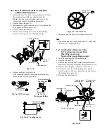
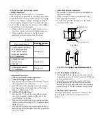
1-6-6. Worm Gear, Worm Gear Holder, Loading Motor

and Worm Wheel Replacement

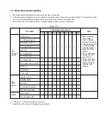
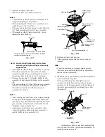
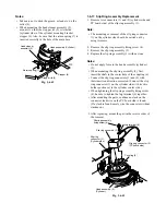
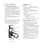
1. Release the claw (1) of the worm gear holder (2) from

the cutout portion of the mechanical deck by
bending it to the arrow direction, and remove the
worm gear holder (2) by pulling downward.

2. Remove the worm gear (3).
3. Before removing the worm wheel (3), first remove the

FL cam gear. (Refer to item 1-6-5.)

4. Remove the worm wheel (4).
5. Remove one securing screw (5) on the loading

motor (6), and remove the loading motor (6).

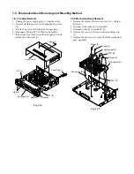
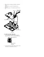
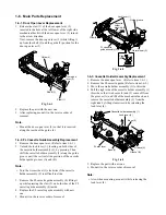
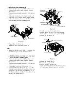
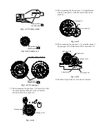
Fig. 1-6-18

Fig. 1-6-13

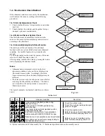
6. Replace each part with new one.

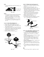
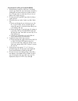
After replacing with new parts, apply an amount of
grease on the following portions.

Fig. 1-6-14  Worm gear

Fig. 1-6-16  Loading motor

Fig. 1-6-17  Worm wheel

7. Mount the parts in the reverse order of removal.

Note:

• After mounting the worm gear holder (2), check that

the claw (1) is locked properly.

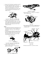
1-6-7. Loading Drive Gear, Cam Slider,

S,  T Loading Lever Assemblies,
Pinch Drive Lever and
Tension Drive Lever Replacement

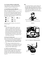
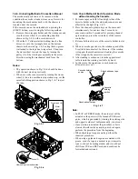
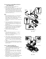
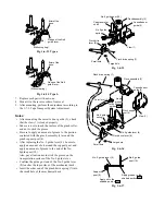
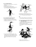
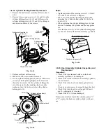
1. Turn the mechanical deck upside down.
2. Remove the reel belt.
3. Remove one securing screw on the joint gear bracket,

and remove the joint gear bracket. (Refer to item  1-6-5.)

4. Remove the joint gear 2. (Refer to item 1-6-5.)
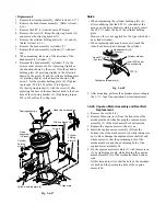
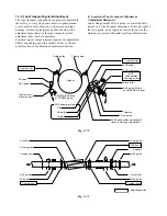
5. Release the claw (1) of the loading drive gear (2)

from the groove of the mechanical deck, and remove
the loading drive gear (2).

6. Remove the cam slider (3).

Loading motor (6)

Claw

(1)

Worm
gear (3)

Worm gear
holder (2)

Worm wheel (4)

Screw (5)

Apply grease to the
shaded portion        .

Apply grease to the
shaded portion        .

Fig. 1-6-15

Worm gear holder

Apply grease to the
shaded portion        .

Apply grease to the
shaded portion        .

Joint gear 1 (6)

Joint gear 2 (8)

Cam slider (3)

T loading lever
assembly (5)

S loading lever
assembly (4)

Loading drive gear (2)

Pinch drive lever pin

Tension drive
lever pin

Claw (1)

Содержание W-707

Страница 1: ...9 VIDEOCASSETTERECORDER SERVICE MANUAL NC MECHANICAL DECK W 707 Aug 2000 Y General Descriptions Adjustment Procedures Servicing Diagrams Parts List General Descriptions Adjustment Procedures Servicing diagrams Part List ...

Страница 2: ...s poten tial exists the fault must be located and corrected Repeat the above test with the VCR power plug reversed NEVER RETURN A VCR TO THE CUSTOMER WITHOUT TAKING NECESSARY CORRECTIVE ACTION The lightning flash with arrowhead symbol within an equilateral triangle is intended to alert the user to the presence of uninsulated dangerous voltage within the product s enclosure that may be of sufficien...

Страница 3: ...SECTION 1 GENERAL DESCRIPTIONS 1 OWNER S MANUAL Top Adjustment Procedures Servicing Diagrams Parts List Parts List Servicing Diagrams Adjustment Procedures Top ...

Страница 4: ...Video Cassette Recorder W 707 OWNER S MANUAL This publication is printed on recycled paper 70971855 PLAY STOP PROG TV POWER EJECT PAUSE STILL REC REV FF ...

Страница 5: ... or modification made to this equipment not expressly approved by Toshiba Corporation or parties authorized by Toshiba Corporation could void the user s authority to operate the equipment Note to CATV system installer This reminder is provided to call the CATV system installer s attention to Article 820 40 of the NEC that provides guidelines for proper grounding and in particular specifies that th...

Страница 6: ...nder inside one of its most crucial internal parts To prevent the VCR from possible damage do not use the unit for at least 2 hours when there is an extreme or sudden change in temperature Compatibility This video cassette recorder VCR is compatible with any other VCR bearing the mark HQ VHS equipment is also compatible with existing non HQ VHS equipment Copyright It is permissible to record telev...

Страница 7: ... operation of the product and to protect it from overheating and these openings must not be blocked or covered The openings should never be blocked by placing the product on a bed sofa rug or other similar surface This product should not be placed in a built in installation such as a bookcase or rack unless proper ventilation is provided or the manufacturer s instructions have been adhered to 5 He...

Страница 8: ... SERVICE EQUIPMENT GROUNDING CONDUCTORS NEC SECTION 810 21 GROUND CLAMPS POWER SERVICE GROUNDING ELECTRODE SYSTEM NEC ART 250 PART H NEC NATIONAL ELECTRICAL CODE S2898A 10 Outdoor Antenna Grounding If an outside antenna or cable system is connected to the product be sure the antenna or cable system is grounded so as to provide some protection against voltage surges and built up static charges Arti...

Страница 9: ...e or electric shock Never spill liquid of any kind on the product 15 Accessories Do not place this product on an unstable cart stand tripod bracket or table The product may fall causing serious injury to a child or adult and serious damage to the product Use only with a cart stand tripod bracket or table recommended by the manufacturer or sold with the product Any mounting of the product should fo...

Страница 10: ...ACK Explains variable functions concerning playback Playback 20 19µ HEAD Variable Speed Playback 21 Picture Search Still Picture Slow motion Picture Frame Advance Double Speed Playback Jog Dial Operation Shuttle Dial Operation Useful Functions in Tape Operation 23 Counter Function Tape Remaining Time Index Search Function RECORDING Explains recording functions Recording a TV Program 25 Watching a ...

Страница 11: ...T c TV POWER SELECT INPUT SELECT VCR TV 1 2 3 DISPLAY COUNTER REMAIN RESET COUNT 4 5 6 TV VCR SP SLP TV VOL A SELECT 7 8 9 0 a CH TRK 8 9 SLOW J PAUSE STILL 100 REC TIMER PLAY STOP F F REW REC VCR Plus POWER CABLE BOX 19µ ENTER CANCEL PROG CH INDEX REV FWD L TV POWER CH TRK CANCEL TV VCR CURSOR RIGHT TIMER TV Number buttons JOG dial SHUTTLE dial SP SLP 20 21 15 19 REW SLOW VCR POWER PAUSE STILL EN...

Страница 12: ... SP SLP Cassette indicator Timer recording indicator REMAIN indicator OFF indicator Hi Fi L R indicators L Left channel R Right channel off Normal track VCR Display POWER indicator DT Digital Auto Tracking indicator Channel indicator Tape running direction speed indicator REMAIN VCR SLP L REC TIMER DT CH H M AM PM OFF S R POWER LINE IN 1 VIDEO jack LINE IN 1 AUDIO jacks L R To wall outlet CH selec...

Страница 13: ...onditions of use If the remote control does not operate correctly replace all batteries with new ones If the remote control is not to be used for a long period of time remove the batteries to avoid possible damage from battery corrosion Caring for the remote control Do not expose the remote sensor of the VCR to a strong light source such as direct sunlight or illumination especially high frequency...

Страница 14: ...Setting the VCR Output Channel When the VCR is connected in this way the VCR sends the output signals to channel 3 or 4 on your TV Set the output channel selector CH selector of the VCR to 3 or 4 whichever is vacant in your area VHF UHF combinaion antenna VHF antenna only UHF antenna only Antenna splitter not supplied 1 2 Connections Before you use this VCR it is necessary to connect it to your TV...

Страница 15: ...isplay and select a desired channel on the TV only when you connect a cable compatible TV This set up will enable you to record an unscrambled channel watch an unscrambled channel while recording it record an unscrambled channel while watching another scrambled or unscrambled You will need to set TV channel to the output channel of the cable box turn on the cable box and select cable channel 3 or ...

Страница 16: ...f the cable box This set up will enable you to watch an unscrambled or scrambled channel while recording it record an unscrambled channel while watching another unscrambled channel only when you connect a cable compatible TV A B switch A record and watch an unscrambled channel which comes bypassing the cable box A B switch B record and watch a scrambled or unscrambled channel coming through the ca...

Страница 17: ... and clock when power is first connected to the VCR Preparation Turn on the TV and select the video channel 3 or 4 or the video input mode if you made the Audio Video connection page 11 Press INPUT SELECT so that the channel number will appear if L1 or L2 is displayed in the VCR display Press VCR to set the remote control operating the VCR Tuning in progress Auto Set Up completed VCR display Notes...

Страница 18: ...the TV 3 Select the language using CURSOR UP or CURSOR DOWN and press PROG The screen turns to the MENU screen 4 Press PROG to return to the normal TV screen Page 23 PREPARATION Initial Settings Using On screen Display Language selection must be set first when the VCR is first plugged in or after it encounters a power failure You can also easily make necessary settings using the on screen displays...

Страница 19: ...HT or CURSOR LEFT Change the data using CURSOR UP or CURSOR DOWN 1 Set SUMMER TIME Daylight Saving Time IN daylight saving time begins on the first Sunday in April Because the clock automatically changes from 2 00 AM to 3 00 AM forward one hour remember that any part of a scheduled Timer Recording that falls between these two times will not be recorded OUT daylight saving time ends on the last Sun...

Страница 20: ...R RIGHT or CURSOR LEFT TV To store channels received via the antenna CATV To store channels received via the incoming cable 5 Select AUTO SCAN using CURSOR UP or CURSOR DOWN and press CURSOR RIGHT to set to On The VCR starts scanning and the channels are stored in the VCR in ascending order When the scanning is finished the screen automatically returns 6 Press PROG to exit PREPARATION Storing Chan...

Страница 21: ...6 47 48 49 50 51 31 32 33 34 35 36 37 38 39 40 41 42 43 44 45 46 47 48 49 50 51 R S T U V W AA BB CC DD EE FF GG HH II JJ KK LL MM NN OO 52 53 54 55 56 57 58 59 60 61 62 63 64 65 66 67 68 69 70 71 52 53 54 55 56 57 58 59 60 61 62 63 64 65 66 67 68 69 PP QQ RR SS TT UU VV WW XX YY ZZ AAA BBB 65 66 67 68 69 70 71 93 94 95 96 97 98 99 100 101 102 103 121 122 123 124 125 93 94 A 5 A 4 A 3 A 2 A 1 100 ...

Страница 22: ...tment This may result in injury or damage Take special care with children to avoid accidents Precautions when using video cassettes Video cassettes have a safety tab to prevent accidental erasure If the tab has already been removed recording cannot be performed To prevent accidental erasure Remove this safety tab with a screwdriver To record again Cover the tab hole with adhesive tape Avoid exposi...

Страница 23: ...ictures while playing back a tape recorded in the SLP tape speed By pressing 19µ repeatedly the 19µ HEAD mode is displayed on the TV screen as follows 19U HEAD AUTO Usually set to AUTO As the playback starts the VCR automatically activates the 19µ head and reproduces high quality pictures 19U HEAD OFF Set to OFF if the pictures are marred by dots Note During playback with the 19µ head momentary no...

Страница 24: ...is frozen This is not a defect in the unit Adjusting Still Picture Stability If the still picture is distorted or flickers hold down one of CH TRK until the picture becomes stable Note The distortion of the still picture may not be eliminated completely Slow motion Picture The tape runs at 1 7th or 1 15th the normal playback speed 1 Press SLOW during playback The tape runs at about 1 7th the norma...

Страница 25: ...ack Jog Dial Operation You can control the speed of frame advance 1 During playback press PAUSE STILL 2 Turn the jog dial on the Remote Control The speed of frame advance varies as you turn the jog dial When you stop turning the dial the picture freezes To cancel the jog dial mode Press PAUSE STILL Shuttle Dial Operation You can also activate the picture search and slow playback at various speeds ...

Страница 26: ...ning Time To view the tape remaining time in the VCR display select the tape length beforehand 1 Turn on the VCR and load a cassette 2 Press PROG to display the MENU screen 3 Select SET UP using CURSOR RIGHT or CURSOR LEFT and press ENTER 4 Select the length of the tape T120 for a T 120 tape or shorter T160 for a T 140 or T 160 tape T180 for a T 180 tape Useful Functions in Tape Operation These fu...

Страница 27: ...n index signal is found the VCR plays back the tape for about 5 seconds and then resumes fast forwarding or rewinding This is repeated each time at an index signal 3 Press PLAY when the desired program is found Normal playback starts Notes At the very beginning of the tape the index search may not work properly If you registered the index signals on a tape recorded on another VCR the recording may...

Страница 28: ... but with less picture and sound quality than using the SP tape speed 5 Press REC on the VCR or simultaneously press both REC on the remote control Recording starts 6 Press STOP to stop recording Recording off time setting By setting the recording off time the recording stops and the VCR is turned off automatically While recording press REC on the VCR repeatedly to set the desired off time Each ti...

Страница 29: ...ord a TV CATV program on the channel not a satellite s If your DSS satellite receiver is not remote controllable choose the desired channel 100 to 999 on the DSS satellite receiver To make corrections Press CURSOR LEFT to move back to the item or CURSOR RIGHT to forward Timer Program Recording The programmable timer allows you to record up to 6 different programs over one month Preparation Select ...

Страница 30: ... tape is long enough for timer program recording in the SP tape speed set the recording tape speed to AUTO Recording starts in the SP tape speed and the VCR automatically selects the tape speed to record the program to the end If the tape length is not long enough the tape speed automatically changes from SP to SLP TIMER POWER PROG 25 8 30 9 30 10 00 E D n On CH DATE OFF D P S PM PMSP PROGRAM SET ...

Страница 31: ...een disappears Changing cancelling the timer programs 1 If the TIMER indicator is lit press both TIMER to turn it off and then turn the VCR on by pressing VCR POWER 2 With steps 2 to 9 change the items To cancel a program select the program you want to cancel in step 4 and press CANCEL The line is then cleared 3 Press both TIMER to return to the timer standby mode Recording or playback in the time...

Страница 32: ...ted local TV publications or the channel guide from cable company If you cannot find the numbers call Gemstar s customer service department at 1 800 4321 VCR Sample of a Guide channel chart from a local TV listing Sample of a Channel line up chart from a cable TV company CHANNEL LINE UP CHART Channel 2 Channel 3 Channel 4 Channel 5 Channel 6 Channel 7 Channel 8 Channel 9 ME U 8 WISH 4 WTTV 6 WRTV ...

Страница 33: ...to exit The set up is all over and your VCR Plus C3 system recording is now available Example Station Your home channel number on the channel line up chart supplied by cable companies Guide channel number on the TV Guide local TV listings etc HBO 33 7 ESPN 34 AMC 35 the case of CATV mode Preparation Select the video channel 3 or 4 or video input mode on the TV If you record cable channels finish t...

Страница 34: ...sure that the clock is set correctly page 16 Load a cassette with a safety tab For cable box users Finish the cable box set up pages 33 36 and turn on the cable box For DSS satellite receiver users This VCR cannot record satellite programs with the VCR Plus C3 system feature To make an unattended recording of satellite programs see Timer Program Recording pages 26 28 Sample of TV program listing i...

Страница 35: ...by mode TIMER POWER Recording or playback in the timer standby mode First press both TIMER to release the timer standby mode and then press VCR POWER to turn on the VCR The VCR will be available for use Be sure to press both TIMER again to return the VCR to the timer standby mode after you have finished Error indications If FULL CANCEL PROG message appears on the TV during programming no more prog...

Страница 36: ... block the sensor window The infrared signals come out of the sensor window and the front of the VCR Then they bounce off walls and other objects in the room and are received by the cable box The VCR sends out infrared signals to your cable box even during timer program recording or VCR Plus C3 system recording Notes If the channels cannot be controlled properly because the infrared signal fails t...

Страница 37: ...able Cable channels will be selected by CH CABLE BOX on the remote control The VCR can change the cable channel to the desired one when timer recording or VCR Plus C3 system recording starts Go to step 7 OFF if your cable box is NON remote controllable Cable channels will be selected by the own channel selector of the cable box The VCR channel should be set to the output channel of the cable box G...

Страница 38: ...hannels in the timer recording In this case set CONTROL to OFF in step 6 The cable box control is not compatible with the DSS satellite receiver control Buttons to control a remote controllable cable box Once you complete the set up for a remote controllable cable box your cable box can be controlled by the following buttons on the remote control of the VCR POWER CABLE BOX To turn the cable box on...

Страница 39: ...0 11 12 13 46 OAK Sigma 10 11 12 13 46 Panasonic 6 8 16 17 Philips 4 13 20 21 22 23 24 25 26 58 62 84 Pioneer 5 6 78 Pulsar 30 42 44 52 63 88 Randtek 13 20 21 22 23 24 25 26 58 62 84 RCA 6 8 16 17 Realistic 44 88 Regal 14 23 41 84 Regency 26 28 Rembrandt 29 32 38 39 42 44 88 Samsung 4 6 32 42 78 Scientific Atlanta 8 9 56 61 Sheritech 27 SL Mark 4 6 32 42 78 Sprucher 6 8 16 17 Stargate 4 6 30 32 42...

Страница 40: ...hown below Do not block the sensor window The infrared signals come out of the sensor window and the front of the VCR Then they bounce off walls and other objects in the room and are received by the DSS satellite receiver The VCR sends out infrared signals to your DSS satellite receiver even during timer program recording Notes If the channels cannot be controlled properly because the infrared sig...

Страница 41: ... receiver is remote controllable Satellite channels will be selected by CH CABLE BOX on the remote control The VCR can change the satellite channel to the desired one when timer recording starts Go to step 7 Preparation Select the video channel 3 or 4 or video input mode on the TV Example TV VCR 1 2 3 4 5 6 7 8 9 0 a 8 9 J PROG REV FWD L POWER CABLE BOX CH CABLE BOX ENTER PROG Number buttons SP SL...

Страница 42: ...t channel of the DSS satellite receiver Go to step 8 7 Select BRAND TYPE using CURSOR DOWN and enter a brand code of your DSS satellite receiver using number buttons Refer to the table on the next page Example For a TOSHIBA DSS satellite receiver identified by number 99 Make sure that the background of the above display has changed to the satellite program on channel 200 If not relocate the DSS sa...

Страница 43: ...nd track Contents of recorded sound On Screen Display Press DISPLAY Setting of SAP SET on the SET UP screen Type of receiving broadcast Normal sound track Mono L R SAP STEREO ON or OFF not lit not lit MONO MONO MONO ON or OFF not lit lit MONO MIXED ON lit not lit MONO MONO SAP OFF lit not lit MONO MONO MONO ON lit lit MONO MONO SAP OFF lit lit MONO MIXED STEREO STEREO Regular monaural audio Stereo...

Страница 44: ...R DOWN and set to ON using CURSOR LEFT or CURSOR RIGHT 2 Press PROG to exit 3 Select the desired channel using CHANNEL on the VCR or CH TRK on the remote control If you use a cable box select a desired channel on the box 4 Select the recording tape speed using SP SLP 5 Press REC to start recording 6 Press STOP to stop recording Broadcast or incoming cable RECORDING To the FM antenna terminal TV VC...

Страница 45: ...te for 100 channel key DISPLAY To turn on or off TV s screen display ENTER To use for the TV s ENTER key Important Some TVs may not respond to all the operations above or may not be operated at all with this remote control In this case operate your TV with its own remote control Notes For some brands several control codes brand codes are allocated Try each of them until the buttons work on your TV...

Страница 46: ...ola 08 MTC 12 NAD 01 11 Nikko 11 Optimus 09 Optonica 08 Panasonic 07 10 15 Penney 01 02 07 11 12 Philco 10 Philips 10 Pioneer 16 Princeclub 12 Prism 07 Proscan 02 Table of Brand Codes Proton 11 Pulser 14 Quasar 07 15 Radio Shack 13 RCA 02 Realistic 09 11 13 Runco NEC 14 Samsung 11 12 Sanyo 09 Scotch 11 Scott 11 Sears 01 02 09 10 11 Sharp 08 13 Sony 03 Soundesign 11 Supreme 03 Sylvania 10 Tandy 08 ...

Страница 47: ...cially available cleaning tape The desired sound is not heard such as SAP stereo or regular sound Setting of sounds is not correct Select a desired sound using A SELECT page 40 Noise is present in the Hi Fi sound being played Tracking is not set appropriately Adjust the tracking manually page 20 The timer recording function does not work There is an error in programming Reset the timer recording p...

Страница 48: ...ront of the VCR page 10 An obstacle may be in the way of the operation Remove the obstacle The operating mode of the remote control is not set correctly Press VCR or TV depending on the equipment you want to operate pages 14 42 The cassette is ejected immediately after it is loaded The cassette was inserted with the label side not paralleling the compartment Reload it carefully page 19 The cassett...

Страница 49: ...minutes When T 160 video cassette is used Fast forward time Within approx 80 s When T 120 video cassette is used High speed rewind time Within approx 54 s when T 120 video cassette is used Video input 1 V p p 75 Ω unbalanced negative sync pin jack Video output 1 V p p 75 Ω unbalanced negative sync pin jack Audio input Line input 308 mV rms more than 47 kΩ pin jack Audio output Line output 308 mV r...

Страница 50: ...n you this product as a gift purchased this product This is one way to enable TACP THI to provide you with better customer service and improved products Failure to return the card will not affect your rights under this warranty Your Responsibility The above warranties are subject to the following conditions 1 You must retain your bill of sale or provide other proof of purchase 2 You must notify an...

Страница 51: ... person agent distributor dealer or company is authorized to change modify or extend the terms of these warranties in any manner whatsoever The time within action must be commenced to enforce any obligation of TACP THI arising under the warranty or under any statute or law of the United States or any state thereof is hereby limited to ninety 90 days from the date you discover or should have discov...

Страница 52: ...vicingTime 1 4 Mechanism Check Method 1 5 Mechanical Deck Removing and Mounting Method 1 6 Main Parts Replacement 1 7 Check and Adjustment 1 8 Self Check Function 2 ELECTRICAL ADJUSTMENT 2 1 PIF Circuit 2 2 Servo Circuit Top General Descriptions Servicing Diagrams Parts List Top General Descriptios Servicing Diagarms Part List ...

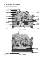
Страница 53: ...E head S slider Tension lever Band brake S reel table FL arm lever S brake Idle lever assembly T slider ACE head Pinch roller Loading motor No 9 guide lever FL cam gear FL drive slider Center gear assembly T reel table T brake No 8 guide cap 1 MECHANICAL ADJUSTMENT 1 1 Mechanical Parts Location Fig 1 1 1 Top view 1 Fig 1 1 2 Top view 2 ...

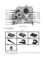
Страница 54: ...S VHS switch Up down lever Joint gear 1 Joint gear 2 Pinch drive lever Worm gear holder 70909401 ST N5 70909203 ST NF 70909103 70909199 70909228 Alignment tape Back tension cassette gauge Torque cassette gauge KT 300NR Taper nut driver VCR cleaning kit VCR lubrication kit Grease Note Conventional alignment tapes MH 1 70909110 MH 1L 70909111 and ST N1 70909202 may be used partly also instead of ali...

Страница 55: ...n post S T slant guide post Impedance Roller No 8 guide post Capstan No 9 guide post No 3 guide post S T guide roller Head assembly cylinder FE head ACE head Pinch roller Capstan motor Loading motor Reel belt Clutch gear assembly Idle lever assembly Band brake Slip ring assembly Note When cleaning use a swab or piece of gauze soaked in alcohol After cleaning load a video cassette with the cleaned ...

Страница 56: ... holder without a cassette Does the T reel rotate with the operation above Does the loading motor and the worm wheel rotate without a cassette after turning the power ON Does the FL cam gear rotate approximate 15 degrees clockwise with the operation above and return immediately Does the VCR stop at the playback position after detecting the tape remain with the cassette with a safety tab inserted L...

Страница 57: ...tive Parts Replacement When a defective occurs due to the defective part s and the part s is replaced take care the following items 1 Especially as for the mechanical parts requiring the phase alignment take care of the part replacement E g Assembling mode phase alignment mark and etc 2 As for the part s requiring lubricant such as a specified amount of oil or grease apply grease or oil according ...

Страница 58: ...ut 2 Check the mechanical position 3 Check the reel belt is removed or not Check mechanical position for the causes 1 2 1 Check capstan motor Check mechanical position for the causes 1 4 1 Check capstan motor 1 Check mechanical position 2 Refer to item 1 4 Mechanism Check Method 3 Check the switch 1 Check capstan motor 1 Check ACE head Check CTL output 1 Check ACE head Check CTL output 2 Perform t...

Страница 59: ...e cassette holder so that the start end sensors are not affected by the light Fig 1 4 7 2 Press the channel up down keys on the main unit simultaneously for not less than 5 seconds in succession within 2 seconds after pressing channel up down keys press the rewind key of the remote controller 3 Release both lock levers of the cassette holder to slot in 4 When a cassette goes down the rotation spee...

Страница 60: ... Mechanical Deck Removing and Mounting Method Fig 1 5 1 Fig 1 5 2 FFC 4 FFC 4 Power Plug 1 Screws 3 Top cover 2 Front panel 5 Claw A Claw A Claw A Screw 3 Screw 3 Connector A Connector B Screw 1 FFC D FFC C Lug terminal 2 1 5 2 Mechanical Deck Removal 1 Remove the cabinet Refer to section 1 5 1 Cabinet Removal 2 Disconnect the connectors A and B 3 Disconnect the FFC C and FFC D 4 Remove the screw ...

Страница 61: ...e chassis 7 Remove the two screws 5 to detach the rear panel 6 8 Remove the screw 7 to detach the main PC board 8 Fig 1 5 3 1 5 3 Mechanical Deck Mounting 1 When mounting the mechanical deck align the marks of the cam switch 1 on the main PC board Fig 1 5 4 2 After mounting the mechanical deck bring it to the state that the cassette holder is just out ...

Страница 62: ...slide position of the cassette holder guide grooves A and B Note Turn the worm wheel 3 clockwise if the cassette holder assembly 2 is difficult to slide 3 Remove the FL cassette guide assembly 4 lifting it up while pressing the claw 5 on both sides of the FL cassette guide assembly 4 inside 4 Replace the FL cassette guide assembly with new one 5 Mount it in the reverse order of removal Fig 1 6 3 5...

Страница 63: ... FL Drive Slider Joint Gear 2 FL Cam Gear and Joint Gear 1 Replacement 1 Remove the door open lever Refer to item 1 6 1 2 Remove the FL cassette guide assembly Refer to item 1 6 2 3 Remove the cassette holder assembly Refer to item 1 6 3 4 Remove the FL arm lever Refer to item 1 6 4 5 Remove the FL drive slider 1 by sliding it to this side slightly and adjusting the mechanical deck boss 2 portion ...

Страница 64: ...r 1 8 mount it so that the cutout portion of the gear is faced with the direction of the FL cam gear 7 Two holes Super V DASH Apply grease to the shaded portion Fig 1 6 10 Joint gear 1 8 Cutout portion FL cam gear 7 Worm wheel 9 Mark Joint gear 1 8 Joint gear 2 6 Cam slider 10 Align marks Align marks Fig 1 6 11 14 When mounting the joint gear 2 6 align the mark of the joint gear 8 with the mark of...

Страница 65: ...m gear holder 2 check that the claw 1 is locked properly 1 6 7 Loading Drive Gear Cam Slider S T Loading Lever Assemblies Pinch Drive Lever and Tension Drive Lever Replacement 1 Turn the mechanical deck upside down 2 Remove the reel belt 3 Remove one securing screw on the joint gear bracket and remove the joint gear bracket Refer to item 1 6 5 4 Remove the joint gear 2 Refer to item 1 6 5 5 Releas...

Страница 66: ...d perform the adjustment and the confirmation of the back tension Refer to the section 1 7 1 Tension Post Position Check and 1 7 2 2 Reel Torque Check and Back Tension Check Fig 1 6 23 12 When mounting the cam slider 3 loading drive gear 2 and the joint gear 2 8 align the marks of the marking portions Fig 1 6 22 Cam slider 11 When mounting the S T loading lever assembly 4 and 5 align the marks Pin...

Страница 67: ...he support post Take care not to dirty bent and damage the felt surface of the band brake 4 8 After mounting confirm the tension post position also confirm the adjustment and back tension Refer to the section 1 7 1 Tension Post Position Check and 1 7 2 2 Reel Torque Check and Back Tension Check 9 After replacing perform the adjustment according to the linearity adjustment of the tape transport sys...

Страница 68: ... Assembly and Up Down lever Assembly Replacement 1 When replacing the center gear assembly 1 and Up Down lever assembly 2 remove the S T brake assemblies and idle lever assembly refer to item 1 6 9 and cam slider refer to Fig 1 6 7 in advance 2 Remove the stop ring 3 fixing the holder clutch assembly 4 and remove the holder clutch assembly 4 3 Release two claws 5 of the Up Down lever assembly 2 fr...

Страница 69: ... to item 1 6 9 2 Remove the band brake Refer to item 1 6 8 3 Remove the S T reel tables 1 and 2 pulling it from the reel shafts 3 and 4 4 Apply an amount of oil to the top portion and sitting portion of the reel shafts 3 and 4 after cleaning the reel shafts 3 and 4 with the cleaning kit 5 Replace each part with new one 6 Mount it in the reverse order of removal S reel table 1 T reel table 2 Reel s...

Страница 70: ...t post and apply an amount of grease to the end of the No 9guide post 10 Also pay attention not to stick the grease on the transportation surface of the No 9 guide lever Confirm the guide post end of the No 9 guide lever 8 touches the top surface of the mechanical deck Insert the other end of the pinch drive spring 7 into the small hole of the mechanical deck a b Flange of the No 9 guide lever Bri...

Страница 71: ... with new one Fig 1 6 39 4 When mounting the ACE head assembly 3 to the mechanical deck mount it by aligning the slit A of the mechanical deck with the slit B of the ACE head bracket 4 after aligning the hole 5 of the ACE head bracket 4 to the boss 6 of the mechanical deck Fig 1 6 40 5 Mount the part in the reverse order of removal 6 After mounting perform the adjustment according to the 1 7 3 Tap...

Страница 72: ... connector 1 on the cylinder side with its wire holder portion set to the cylinder center side When tightening the slip ring assembly fixing screw 4 be sure to tighten the lug terminal 6 together After mounting the parts confirm no slack on the connector lead wire on the PC board side is found If a slack is found surely wire the connector without slackened 5 After replacing mount the part in the r...

Страница 73: ...1 to 5 replace the head assembly cylinder with new one Be sure that driver does not approach to cylinder Screwdriver Cylinder holding plate 5 Screw 3 Head assembly Cylinder 1 6 18 Cylinder Holding Plates Replacement 1 Remove the head cleaner assembly Refer to item 1 6 16 2 Remove three securing screws 1 2 and 3 on the cylinder holding plates 4 5 and 6 Remove the cylinder holding plates 4 5 and 6 b...

Страница 74: ... Screw 2 Fig 1 6 47 Notes When remounting the cylinder holding plate 4 after confirming that the FPC 1 is hooked at the groove on the lower head assembly properly insert the FPC 1 under the tip of the cylinder holding plate However this is not applied for the type which has no cylinder window When replacing take much care not to touch the video head directly and damage the cylinder Hook FPC on the...

Страница 75: ...ts the imped ance roller to prevent from pulling out So when standing the unit with its top cover removed be sure to remove the impedance roller in advance Do not touch the tape running portion on the roller surface directly by hand and do not attach oil etc on it S impedance roller assembly 1 Apply oil Shaft 2 Fig 1 6 52 Screws 2 Positioning hole of capstan motor assembly Capstan motor assembly 3...

Страница 76: ...rque will cause damage to the tape during REVIEW mode 2 REC PLAY take up side Poor torque does not rewind the tape to the end If excessive torque the tape may be stretched by excessive tension 3 Inspection Rewind the torque cassette to the end then check the torque value shown below Review SP x7 14 2 3 9 mN m 145 40 g cm REC PLAY 8 1 2 7 mN m 82 5 27 5 g cm For the checking method refer to the fol...

Страница 77: ...e tape is not slackened If slackened operate the VCR in CUE or REVIEW mode and then stop the tape Then make sure the tape is not slackened again 3 After above confirmation proceed to the real torque adjustment and confirmation 4 Caution for removal of torque cassette 1 When removing the torque cassette from the VCR set the VCR to the STOP mode and wait for several seconds Then make sure the tape i...

Страница 78: ...ge height of No 8 guide is used as the basic reference for the transport adjustment To keep height of the No 8 guide do not apply excessive force onto the main base to prevent the main base from deformation Pinch roller S guide roller S slant guide T slant guide T guide roller FE head No 3 guide Tension lever tension post REVIEW Released at FF REW mode ACE head No 8 guide ACE head position adjusti...

Страница 79: ...al on the alignment tape Trigger scope with switching pulse Adjust tracking control for maxi mum envelope output by pushing tracking up down buttons Playback stereophonic alternative recording signal 300 500Hz on alignment tape Turn the Audio height adjusting screw until audio envelope signal becomes as flat as possible 2 AUDIO HEAD TILT FINE ADJUSTMENT 4 AUDIO HEAD AZIMUTH FINE ADJUSTMENT Playbac...

Страница 80: ...ew until tape wrinkle is caused at the lower flange of No 8 guide as shown in Fig 1 7 6 A 3 Turn the ACE tilt adjusting screw counter clockwise until the tape travels along the lower flange as shown in Fig 1 7 6 B Adjustment proce dure From item a From item c From item d Parts replacement Head assembly Cylinder S T sliders assembly ACE head assembly Pinch lever assembly No 9 guide lever Impedance ...

Страница 81: ...just T guide roller in up or down direction A B Fig 1 7 8 Adjusting section 6 After completion of the adjustment s push the tracking up down button and make sure video envelope variations are almost flat Next playback the 2 MHz A ch SP mode video signal on the alignment tape and make sure the video RF envelope variations are also flat when tracking up down buttons is pushed NG NG OK Fig 1 7 9 Abno...

Страница 82: ... the SLP mode at the tracking center difference between the track ing position of maximum envelope in the SP mode and the tracking center is within 3ms 7 Tighten the ACE head position fixing screw and secure the ACE main base g After Completion ofACE Head FineAdjustment Apply screw lock to two screws tilt azimuth adjusting screws in front of the ACE head 5 No 9 Guide Lever Check 1 Set the VCR to C...

Страница 83: ...se difference among each maximum point of AFM envelope A ch and B ch is within 3 ms with the above point used as the basic reference Note If the phase difference exceeds 3 ms replace the head assembly cylinder A B B A 0 55 B 120mV Fig 1 7 12 Envelope output and output difference 3 If the performance does not meet both specifications above 1 and 2 above replace the head assembly cylinder assembly 4...

Страница 84: ...e playback Still in reverse playback Reverse slow playback Recording Record pause Power off eject Eject Short FF Short REW Cylinder stop Reel abnormality take up Reel abnormality supply Abnormal slot in slot out Abnormal loading F L driving Loading unloading Reverse rotation with pinch roller ON Playback with pinch roller ON Stop with main brake ON Position detection impossible FF REW Abnormal sys...

Страница 85: ... system 3 Frequency counter 7 digits or higher 4 Millivoltmeter 5 Digital voltmeter 6 Tester 20 kΩ V 7 Audio generator 8 Audio attenuator 9 Alignment tapes Part code ST N1 70909202 ST NF 70909203 ST N5 70909401 10 Alignment screw driver jig 11 Color pattern generator 12 Video sweep generator Color bar signal Color bar signals of 75 recorded on the alignment tapes are shown in Fig 2 1 1V p p 0 7V 0...

Страница 86: ...ck and adjustment of Video circuit Check and adjustment of Servo circuit Notes 1 This signal is used for tape running adjustment also 2 Set tracking control to center When making linearity adjustment set tracking control to the position where envelope obtains max 1 1 1 2 1 3 1 4 1 5 SP SP SP EP SLP EP SLP 10 min 10 min 9 min 5 min 5 min Item No Mode Time Record Contents Video signal Notes This sig...

Страница 87: ...signal is used for tape running adjustment 2 Set tracking control to center position except linearity adjustment 3 When making linearity adjustment S T guide roller set tracking control to the position where envelope obtains max Check and adjustment of Servo circuit Notes 1 This signal is used for tape running adjustment also 2 Set tracking control to center When making linearity adjustment set tr...

Страница 88: ...n on the remote control unit 3 The following data will be set in the corresponding address as tabulated 4 Press power button to set the unit to power off mode 5 Pull out the power cord plug from the AC outlet once and insert the power cord plug into the AC outlet again 6 The initialization of default data for MTS IC is now completed The above mentioned procedure will only change the software setti...

Страница 89: ... the video out signal 2 2 2 Pseudo V Test point Tracking UP DOWN key Test equipment TV monitor 1 Self recorded tape in SP mode is played and enter STILL mode 2 When tracking UP DOWN key is pressed the center of STILL picture should be adjusted with STILL condition Turn off the VCR When turning off the VCR pseudo V data will be written into EEPROM Note Do not pull out the POWER CORD the data will b...

Страница 90: ...rement 6 PRINTED WIRING BOARD AND SCHEMATIC DIAGRAM 7 BLOCK DIAGRAMS 7 1 Power Supply Block Diagram 7 2 PIF Block Diagram 7 3 KDB Display Block Diagram 7 4 EDS Block Diagram 7 5 Servo Logic Block Diagram 7 6 Video and Conventional Audio Block Diagram 7 7 Hi Fi Audio Block Diagram 8 CIRCUIT DIAGRAM 8 1 Waveform 8 2 Circuit Diagram 9 PC BOARDS 9 1 Main PC Board UZ01 9 2 FCB PC Board UK02 9 3 JSB PC ...

Страница 91: ...io PLAY system Servo system Video PLAY system Audio PLAY system Servo system Table 1 1 1 INSPECTION PROCEDURES Items to be confirmed Clock display Clock setting operation Mode display lamp TV receive condition Channel select operation EE picture and tone quality Signal level Stereo operation Cassette loading operation Eject operation Indicator lamp Abnormal sound Each mode operation Tape drive ope...

Страница 92: ...anel 5 Claw A Claw A Claw A 3 IN 1 Tuner UK02 FCB PC Board UK03 JSB PC Board UZ01 Main PC Board UZ01 Main PC Board UK02 FCB PC Board UK03 JSB PC Board Fig 4 1 4 PC BOARD SERVICING PRO CEDURE When performing service connect each connection part of the mechanical deck with the main PC board two connectors two flexible flat cables and then turn the unit upside down with the mechanical deck integrated...

Страница 93: ...ement RF Fusible Table 5 2 1 5 3 Capacitance Indication Symbol Electrolytic Special electrolytic Non polarity electrolytic Ceramic plastic Film Trimmer Unit None F m µF p pF Rated voltage None 50 V For other than 50 V and electrolytic capacitors described in the Circuit Diagram Tolerance 1 Ceramic plastic and film capacitors of which capacitance are more than 10 pF None 5 or more B 0 1 C 0 25 D 0 ...

Страница 94: ...olor circuits was conducted with sufficient service color bar signal being received and reproduced in normal conditions Waveforms and voltage values for the remaining circuit were measured with a broadcasting signal normally received so they may vary slightly according to the programs being received Use them as a measure for servicing All voltage values except the waveforms are expressed in DC and...

Страница 95: ...CTL HIFI CTL GND VIDEO V SWP 2 4 LINE 2 L IN FFC P970 EJECT SW DIGITAL GND F A V LED F A V SW W501A AUDIO GND VIDEO GND LINE 2 V IN NC 13 11P W503 AFM ENV P101 P102 LINE 2 R IN P702 5 P801 W701 70175750 AC 120V 60HZ EVER 5 6V 70175751A 23164503 W101 70175754 23902362 70165328 1 3 5 6 7 8 9 10 11 POWER SW EVER 5V 2 4 LINE 2 L IN EJECT SW DIGITAL GND F A V LED F A V SW AUDIO GND VIDEO GND LINE 2 V I...

Страница 96: ...1 R803 D806 CONTROL SWITCHING Q801 Q802 GENERATOR AC CLOCK R870 D870 Q870 R871 6 3 2 1 9 8 16 15 14 13 SWITCH MODE TRANSFORMER SMOOTHING RECTIFIER SMOOTHING RECTIFIER SMOOTHING RECTIFIER T802 SMOOTHING RECTIFIER 5V REG Q831 Q832 VKK 26V EVER 37V F1 F2 EVER 14V BU 5V EVER 5V 5VS AC CLOCK D826 C826 C827 D827 C825 D825 C821 D821 C823 D822 C813 9V REG Q841 9VS 5V REG Q843 D820 RECTIFIER SMOOTHING 7 C8...

Страница 97: ...HA11560FP MIX OSC AJ605A IF MODULE 4 5MHz BPF LPF TUNING TUNING RF AMP RF RF AMP AMP AMP DET AMP RF MODULATOR TUNE IF PIF SIF LA7578N 7 INPUT ATTENUATOR DEMODULATION SAP SWITCH STEREO SAP INTERFACE 1 C BUS BLOCK BLOCK DEMODULATION STEREO REDUCTION BLOCK DBX NOISE ABSORPTION OFFSET D A 15 16 MATRIX SELECTOR 26 25 27 CONVENTIONAL AUDIO OUT 3 IN 1 TUNER ICD01 µPC1854AGT MULTIPLEXED TELEVISION SOUND P...

Страница 98: ...TE CONTROL EVER 5V DET PEAK WAVEFORM SHAPER 8 2 5 1 2 3 1 LED DRIVER SWITCH QX31 QX30 DX32 DX31 IC501 TMP93CU76 MAIN MICROCOMPUTER 21 20 24 23 22 25 46 KEY 2 PLAY CH DOWN PAUSE KEY 1 REC STOP CH UP 54 55 6 57 56 29 28 19 18 17 16 15 14 13 12 11 10 9 8 7 6 42 FIP DRIVE F F WK31 UK03 JSB 70145518 SHUTTLE ZX01 25U39149SAN 1 2 4 5 6 7 8 9 10 17 18 19 20 21 22 23 24 25 26 27 28 29 30 31 32 34 35 F F 6G...

Страница 99: ...E IN 28 29 25 IC501 TMP93CU76 MAIN MICROCOMPUTER 48 42 KEY INPUT 1 B1 B2 Shuttle Seg 1 Seg 2 Seg 3 Seg 4 Seg 5 Seg 6 Seg 7 Seg 8 Seg 9 Seg 10 Seg 11 Seg 14 G1 G2 G3 G4 G5 G6 Seg 12 Seg 13 Seg 15 Seg 16 PLAY STOP Key 1 EJECT CH DN CH UP PAUSE REC Key 2 POWER L Active H Active Unlatch Key Simultaneous Pushing Permitted ECO ECO LED ...

Страница 100: ...4 P15 P16 6G 5G 4G 3G 2G 1G 1d 1e 1c 1g 1f 1b B1 1a B2 B3 2d 2b 2c B4 2e B5 2c 2g 2f 2b 2a 3b 3c 1b 1a 1f 1c 1g 1e 1d 1b 1a 1f 1c 1g 1e 1d 1b 1a 1f 1c 1g 1e 1d 2a 2b 2f 2g 2c 2d 2e 2a 2b 2f 2g 2c 2d 2e col B3 B2 B1 B4 B5 2a 1a 3b 3c 2b 2c col 1a 2a 1a 1f 1e 1b 1c 1g 1d 2a 1a ...

Страница 101: ...y RAM MUX Address Latch Display Control Port Serial 14 15 4 6 Stetus Rag Test Rag Row Command Processor CW SLS SFLD LS FLD Line Field Decodes M SYNC 8 7 Buffer VIDEO IN CSYNC Slice Level SIG SYNC COMP DIV CLK DOT CHAR CLK DOT CLK Slicer Data PG Lock 16 Sliced Data SMS FEW Data Bus 13 SEN SCK SDA SDO Row Latch 4 8 13 4 6 10 DEC ADDR 9 5 HSYNC LPF Loop Filter 1 11 Vss Vss A VW VIN Intro SCL 1 SDA 1 ...

Страница 102: ... PV PH 38 EE PB TRICK 89 A MUTE 30 REC H 91 INSEL 1 92 INSEL 2 5 6 7 6 3 2 9 1 5 CONTROL CIRCUIT 5 1 2 16 15 11 6 10 REG 7 8 9 BRIDGE DETECTOR 42 DX32 DX31 QX30 QX31 55 54 I P SHUTTLE JOG 5V REC CTL 13 14 15 16 17 18 24 23 22 21 20 19 Vcc2 Vcc1 REG 2 1 3 5 4 8 6 7 9 10 11 12 Vcc2 SW 5V CONTROL GAIN EVER 5V OSD STB OSD DATA OSD CLK TO OSD IC POWER SW KEY IN 2 57 KEY IN 1 56 46 RMT IN 68 SP LP EP 76...

Страница 103: ...L REFERENCE ADGND ANALOG DIGITAL GROUND CAM C CAM B CAM A CAM SWITCH A INPUT FOR MECHANICAL POSITION DETECTION VIDEO ENV DET VIDEO ENVELOPE A D INPUT FOR AUTO TRACKING HIFI ENV DET AUDIO ENVELOPE A D INPUT FOR AUTO TRACKING AFT AUTO FINE TUNING LOCK DETECTION KEY IN2 KEY MATRIX INPUT KEY IN1 KEY MATRIX INPUT SHUTTLE 3 4 SHUTTLE POSITION INPUT SHUTTLE 1 2 SHUTTLE POSITION INPUT IIC BUS CLK IIC BUS ...

Страница 104: ... 68 1 2 4 5 32 34 35 36 37 38 39 Pin NO MAIN POWER OFF L L L L L L L L L L L L L L L L L L L L H L L L L L OPEN REMOTE POWER OFF L L L H L L L L L L L L L L L L L L L L L L OPEN OPEN REC PAUSE SP EP L L L L L L H L H L L L L L H H L H H REC SP SLP L L L L H H L H L L L L L H H L H H SLOW SP SLP L L L PWM L L H L L L H H 3ST L H H STILL SP SLP L L L L L L H L L L L H H L H 3ST L H H OPEN REV SP SLP...

Страница 105: ...D REWIND REWIND REWIND STOP SHORT SHORT STOP STOP STOP VISS VISS SEARCH SEARCH EJECT EJECT EJECT EJECT EJECT EJECT EJECT EJECT EJECT EJECT EJECT EJECT 5 REC PAUSE PAUSE REC STILL STILL PLAY STILL REC REVIEW REVIEW REVIEW REVIEW REVIEW REVIEW REVIEW 3 4 CUE CUE CUE CUE CUE CUE CUE 2 1 FEEDING FRAME X2 END TAPE MAIN POWER RESET COUNTER INDEX TIMER COUNTER EJECT REC PAUSE SLOW REW FF PLAY STOP 5 4 3 ...

Страница 106: ... TRAP fH MUTE REC 73 74 78 68 PB PB 9dB REC AMP DIV ALC AMP AMP R P R P AMP PB ACK P R P R AGC AMP P R R P R P R P P R R P P R ACK PB SP TRICK P R P 16dB X401 SP B VIDEO 4 5 SLP A SP A P101 SLP B MAIN DE EMPH REC Y C PB Y C DE EMPH CIRCUIT AUDIO PB REC FE HEAD AE HEAD BIAS GENERATOR SWITCH HEAD 5 4 6 2 AUDIO REC AUDIO PB CONVENTIONAL AUDIO PB CONVENTIONAL AUDIO REC TUNER AUDIO N HIFI AUDIO Q206 VI...

Страница 107: ...ECTOR L SELECTOR R OUTPUT INPUT SELECTOR DECODER I C BUS 45 47 41 43 DECODER I O MEMORY BUS BPF ADJ 2 IC920 TA1246F HIFI PROCESS SDA1 SCL1 HIFI ENV HIFI DET OUT PB HIFI FM REC HIFI FM AUDIO FF TO SERVO LOGIC PRE REC CTL ICV61 TUNER AUDIO L MOD AUDIO TUNER AUDIO R ATT ATT REC EE SIGNAL L REC EE SIGNAL R PLAY EE SIGNAL L PLAY EE SIGNAL R LINE IN 1 L R LINE IN 1 LINE OUT L LINE OUT R TO PIF ATT ATT 3...

Страница 108: ...OR INPUT REC SYSTEM 30 20 40 7 75 24 5 77 5 50 2 45 OUTPUT LINE AMP 70 0 25 0 78 60 2 45 50 7 75 40 24 5 30 77 5 20 245 10 775 0 mV rms dB 8 308 REC SYSTEM INPUT 400Hz 308 mV rms INPUT SELECTOR INPUT REC AMP INPUT AMP LINE OUTPUT LINE OUTPUT OUTPUT AMP REC INPUT AUDIO HEAD HEAD OUTPUT AUDIO OUTPUT AMP EQ PLAY SYSTEM ELECTRO MAGNETICS CONVERSION LOSS CONVENTIONAL AUDIO LEVEL CHART EE ...

Страница 109: ...C501 a Pin 34 b Pin 35 V 2V div H 5µs div a b SP PLAY a b a b a b J 12 J 12 34 IC506 Pin 17 V 500mV div H 500µs div CFGB AMP SP PLAY G 7 26 IC501 Pin 43 V 1V div H 10ms div REC CTL OUT REC J 12 I 10 35 IC501 a Pin 70 b Pin 69 V 2V div H 100ms div H 10 I 10 27 IC501 Pin 78 V 1V div H 20µs div 36 IC501 a Pin 52 b Pin 53 V 2V div H 200µs div I 11 I 11 F 13 F 14 28 IC501 Pin 74 V 1V div H 0 5µs div I ...

Страница 110: ...01 15 JPF03 20 JP004 20 JP010 12 5 JP705 17 5 JP617 12 5 JP917 7 5 JP582 12 5 JP911 12 5 JP912 10 JP260 7 5 JP259 7 5 JP602 10 JP612 10 JP611 20 JP622 10 JP558 10 JP559 20 JP623 12 5 JP202 12 5 JP535 12 5 JP526 7 5 JP903 7 5 JP235 7 5 JP277 15 JP238 7 5 JP219 15 JP229 5 JP228 10 JP225 20 JP212 15 JP242 15 JP227 5 JP249 5 JP240 12 5 JP610 12 5 JP711 5 JP715 12 5 JP203 10 JP201 10K R845 KESTU R850 7...

Страница 111: ...C720 KETSU R720 KETSU R721 0R R251 RN1404 Q254 0R R263 KETSU R262 22µ L209 KETSU C778 301 KETSU R216 27p C210 1 5k R211 1k R210 1k R213 100 R212 10k R296 4 7k R297 KETSU CL10 F0 01µ C204 1µ50V C715 ETSU KETSU C279 F0 01µ CL14 3 9K RL21 2µ C 4 7k RL12 F0 01µ CL12 CL13 ICL01 D844 22µ16V C843 22µ16V C844 620 R844 MTZJ5 6C D843 2SC2236Y Q843 KETSU R266 15p C276 F0 01µ C278 3 KETSU C261 27K 10K R719 4 ...

Страница 112: ... 100 R407 2SA1162Y Q411 KETSU 847 7 5 256 k 7 B0 01µ C299 470 R298 470 R299 4 7k R532 4 7k R531 KETSU DF01 KETSU C105 2M2 R232 68p C232 ERA15 02 D506 15 02 507 F0 01µ C301 2 2k R569 2 2k R568 10k R570 KETSU C562 P506 SU 9 10µ16V CF05 10µ C KETSU CF03 F0 01µ CF04 MM1113XS ICF01 1k R102 100 R101 1k R107 2µ250V C238 47µ16V C514 R507 47µ16V C545 R512 22µ35V C548 B0 01µ C547 47µ16V C513 56k R511 SL100p...

Страница 113: ...F841 10K R842 10µ L302 4µ7 C303 100n C302 6n8 C305 22k R306 22k R304 470 R303 470 R302 2SC2712Y Q301 3 CD 10µ CD16 1µ CD17 1µ CD18 47µ CD02 22µ CD03 0 1µ CD04 10n CD01 10 RD 1k RD01 4µ7 CD06 1µ CD05 2 C KETSU C007 0R R010 KETSU D002 10µ10V C002 0 022µ C006 10k R007 4 7K R006 Q001 23344082 S001 1KF R001 1K R002 H001 3K9 R004 3K9 R005 10µ16V C005 PL 10µ L002 27K R003 4µ716V C003 47µ50V C004 D001 10µ...

Страница 114: ... 9 0 0 2 3 0 0 9 1 2 1 2 1 2 1 0 1 4 2 2 2 0 8 2 2 0 4 0 2 0 4 4 5 0 2 4 5 4 5 4 6 4 5 0 9 0 9 0 9 4 5 4 4 4 5 0 5 0 4 0 5 4 9 4 9 4 9 4 9 4 9 4 9 4 9 4 9 4 9 4 4 4 4 4 4 4 4 4 4 4 4 4 4 4 4 4 4 4 4 4 4 4 4 4 4 4 4 4 4 4 5 4 4 4 4 4 4 4 5 4 5 4 5 4 5 4 5 4 5 4 5 4 5 4 5 4 5 4 5 4 5 4 5 4 5 4 5 4 5 4 5 4 5 4 5 4 5 4 5 4 5 4 5 4 5 4 5 4 5 4 5 4 5 4 5 4 5 4 5 4 5 4 5 4 5 4 5 4 5 4 5 4 5 0 0 0 0 0 0 0...

Страница 115: ...1A 2SK2185 Q801 1KV 180P C813 2W 47K R803 µPC1093J Q825 125V200mA F802 MTZJ5 1A RD5 1ESAB1 D813 ERA15 02 D812 L823 100 C C832 EL1Z D820 D D 270 R823 RF827 C826 C827 C825 AG 01 D826 AG 01 D827 AG 01 D825 C811 ON3131 RTH Q804 T802 ERA15 02 D804 ERA15 02 D803 ERA15 02 D802 ERA15 02 D805 T801 1KG R822 4 7KG R821 2k R808 220µ10v C824 C821 L822 L821 C823 220µ25V C822 RU2YX D821 100 R807 0 012µ C808 510K...

Страница 116: ...C837 C832 D830 D829 D828 RF827 C826 C827 C825 v 4 L821 220µ25V C822 120p C539 4 7k R532 4 7k R531 LY89 ERA15 02 D506 ERA15 02 D507 ERA15 02 D510 1SS226 D501 SL120p C540 KETSU C541 10k R538 10k R540 10k R539 B0 01 C527 2 2k R569 2 2k R568 47µ6 3V C561 10k R570 KETSU C562 KETSU C563 B0 01 C592 4K7 R549 4K7 R548 Q601A D601A 10K R537 47µ6 3V C504 1k R546 1k R547 47µ16V C514 4 7k R507 820 R502 47µ16V C...

Страница 117: ...0 0 0 RVO MODE TCH TRANSISTOR PHOTO DRUM MOTOR DRIVER PROCESSOR AUDIO HIFI P 3 10 32 6 5 22 23 24 25 26 27 28 29 9 8 7 2 1 F P16 P15 P14 P13 P12 P11 P10 P9 P8 6G 5G 4G 3G 2G 1G RX17 RX27 17 5 JP617 12 5 JP917 10 JP612 10 JP611 20 JP622 10 JP558 10 JP559 20 JP623 7 5 JP904 10 JP918 17 5 JP708 10 JP906 7 5 JP905 15 JP709 100µ16V C966 SX01 4 7K R575 S602 10µ16V C940 2 2k R599 47 RX05 20 E81 5 E82 1k ...

Страница 118: ... 5 2 5 2 5 2 5 2 5 2 5 2 5 2 5 2 5 2 5 2 5 2 5 2 5 2 5 2 5 2 5 2 5 2 5 2 5 2 5 2 5 2 5 2 5 2 5 2 5 2 5 0 0 0 0 0 0 0 0 0 80 68 67 66 65 69 70 78 79 77 76 71 72 73 74 75 62 61 60 59 58 57 56 50 51 52 53 54 55 64 63 2 8 2 8 2 6 2 5 1 9 1 9 4 4 4 4 4 7 4 7 0 0 2 4 2 4 2 4 2 3 0 4 5 2 4 2 3 4 9 4 9 4 9 4 9 4 9 4 9 4 8 0 4 9 4 9 4 9 4 9 0 0 4 8 4 8 1 9 1 9 2 2 2 2 1 5 1 5 1 2 1 2 4 9 4 9 0 5 0 5 0 8 0 ...

Страница 119: ...825 C826 C827 C828 C829 C831 C832 C833 C834 C837 C841 C842 C843 C844 C920 C921 C922 C923 C926 C928 C929 C930 C931 C932 C933 C934 C935 C936 C937 C938 C939 C940 C942 C963 C966 C969 C971 CD02 CD03 CD05 CD06 CD07 CD08 CD10 CD12 CD13 CD14 CD15 CD16 CD17 CD18 CE61 CF02 CF03 CF05 CF90 CF91 CH11 CL11 CL13 CL16 CW90 CX04 D001 D202 D203 D204 D503 D506 D507 D508 D509 D510 D601 D801 D802 D803 D804 D805 D806 D...

Страница 120: ...9 2 FCB PC Board UK03 1 A 2 3 4 9 3 JSB PC Board UK03 Fig 9 3 1 Fig 9 2 1 B C 1 A 2 3 4 B C CK99 JPK91 JPK92 JPK93 JPK94 JPK95 JPK96 P998 P999 PK98 PK99 SK21 SK22 W970A WK11 DK30 W960A WK31 ...

Страница 121: ...citor Cap 3 3 Resistor Res 4 EXPLODED VIEWS 4 1 Packing Assembly 4 2 Cabinet Assembly 4 3 Chassis Assembly 4 4 Mechanism Assembly 1 4 5 Mechanism Assembly 2 5 PARTS LIST Top General Descriptions Adjustment Procedures Servicing Diagrams Top General Descriptions Adjustment Procedures Servicing Diagrams ...

Страница 122: ...f chip type and mounted on original PC boards However when they are placed for servicing works use discrete parts listed on the parts list 3 ABBREVIATIONS 3 1 Integrated Circuit IC 3 2 Capacitor Cap Capacitance Tolerance for Nominal Capacitance more than 10pF P 100 0 Symbol Tolerance B 0 1 C 0 25 D 0 5 F 1 G 2 J 5 K 10 M 20 N 30 V 20 10 W 100 10 U 75 10 Q 30 10 T 50 10 Symbol Tolerance X 40 20 Y 1...

Страница 123: ...P801 Y101 Y102 Y103 Y104 Y107 Y111 Y112 Y113 A701 A702 A703 4 EXPLODED VIEWS 4 1 Packing Assembly Fig 4 1 1 4 2 Cabinet Assembly Fig 4 2 1 A104 A104J A102C A101 A106 A101H A106A UK03 A101D UK02 ...

Страница 124: ...4 3 Chassis Assembly Fig 4 3 1 B001A UZ01 B603B B603C B603 A105 ...

Страница 125: ... 4 1 G051 G050 G532 G530 G540 G538 B256 B254 G053 G052 G536 G534 B239 G510 G480 G663 G666 G555 B474 K546 G527 G520 B460 B462 B456 B458 B473 B468 B500 B484 B488 B464 B478 G661 G428 G420 G450 G458 U190A G104 G101 G101A G001 U190 G102 ...

Страница 126: ... 5 Mechanism Assembly 2 Fig 4 5 1 B248 K490 K502 K250 K330 K544 K544 K542 K350 K340 K110 K140 K248 K240 K530 K180 B570 B444 B446 B448 B440 B452 K470 B560 K544 B238 B410 G542 K219 K221 KC02 K224 G546 K200 ...

Страница 127: ... B603B 70391703 Screw 3x6mm B603C 70391973 Screw 3x12mm G001 70311583 Cylinder Assy G050 70125736 Slip Ring Assy G051 23721310 Screw 3x10mm G052 70372085 Bracket G101 70311585 Upper Cylinder Assy G104 70368260 Coupling G420 70300455 S Slider Assy G426 70847076 Bush G450 70322537 T Slide Assy G480 70318793 ACE Head Assy G510 70391936 Screw 2 6x5 6mm G520 70343273 No 9 Guide Lever Assy G522 70343274...

Страница 128: ... 70391847 Screw 2 6x8mm KC02 70361720 Holder FL Cassette Guide Y101 70971855 Owner s Manual English Y104 70061209 Sheet Extended Service Plan Y112 70148471 Remote Control Unit Y113 70168298 RF Cable LOCATION NUMBER PART NUMBER DESCRIPTION ...

Страница 129: ... R TRANSISTORS Q001 A6335470 Transistor Chip 2SC2712 Y Q210 A6548370 Transistor Chip 2SA1362 GR Q211 A6335470 Transistor Chip 2SC2712 Y Q251 A6335470 Transistor Chip 2SC2712 Y Q252 A6335470 Transistor Chip 2SC2712 Y Q254 A6004040 Transistor Chip RN1404 Q301 A6335470 Transistor Chip 2SC2712 Y Q410 A6335470 Transistor Chip 2SC2712 Y Q411 A6541130 Transistor Chip 2SA1162 Y Q510 A6004040 Transistor Ch...

Страница 130: ... 23316690 Diode Zener MTZJ10B D843 23316673 Diode Zener MTZJ5 6C D870 23118486 Diode ERA15 02 D940 23115537 Diode 1SS131 DH11 23118486 Diode ERA15 02 DL11 23115537 Diode 1SS131 DL12 23115537 Diode 1SS131 DX31 70118324 Diode LED TLN105B DX32 70118324 Diode LED TLN105B COILS L001 23289479 Coil Peaking TRF44R7AF L002 23289100 Coil Peaking TRF4100AF L101 23289180 Coil Peaking TRF4180F L202 23289109 Co...

Страница 131: ... 50V C265 24781241 Cap Chip 240pF J 50V C268 24092178 Cap Chip 0 1MF K 25V C270 24797010 Cap Electrolytic 1MF M 10V C271 24092178 Cap Chip 0 1MF K 25V C273 24815103 Cap Chip 0 01MF K 50V C276 24781150 Cap Chip 15pF J 50V C278 24814103 Cap Chip 0 01MF Z 50V C299 24815103 Cap Chip 0 01MF K 50V C301 24814103 Cap Chip 0 01MF Z 50V C302 24092178 Cap Chip 0 1MF K 25V C303 24630023 Cap Electrolytic 4 7MF...

Страница 132: ...lectrolytic 1MF M 10V C716 24815333 Cap Chip 0 033MF K 50V C717 24797010 Cap Electrolytic 1MF M 10V C771 24082049 Cap Plastic 0 047MF J 100V C772 24794470 Cap Electrolytic 47MF M 16V C773 24815103 Cap Chip 0 01MF K 50V C774 24815103 Cap Chip 0 01MF K 50V C775 24794330 Cap Electrolytic 33MF M 16V C776 24214221 Cap Ceramic 220pF K 500V C777 24815103 Cap Chip 0 01MF K 50V C801 24082926 Cap Plastic 0 ...

Страница 133: ... Electrolytic 0 47MF M 50V CD11 24092178 Cap Chip 0 1MF K 25V CD12 24630034 Cap Electrolytic 1MF M 50V CD13 24630034 Cap Electrolytic 1MF M 50V CD14 24630034 Cap Electrolytic 1MF M 50V CD15 70415176 Cap Electrolytic 3 3MF F 16V CD16 70415177 Cap Electrolytic 10MF F 16V CD17 24630034 Cap Electrolytic 1MF M 50V CD18 24630034 Cap Electrolytic 1MF M 50V CE61 70430002 Cap Electrolytic 1000MF CF02 24794...

Страница 134: ...J 1 16W R403 24872273 Res Chip 27kohm J 1 16W R405 24872222 Res Chip 2 2kohm J 1 16W R406 24872102 Res Chip 1kohm J 1 16W R407 24872101 Res Chip 100ohm J 1 16W R408 24872102 Res Chip 1kohm J 1 16W R501 24872103 Res Chip 10kohm J 1 16W R502 24366821 Res Carbon 820ohm J 1 6W R503 24872471 Res Chip 470ohm J 1 16W R504 24872224 Res Chip 220kohm J 1 16W R505 24872474 Res Chip 470kohm J 1 16W R506 24872...

Страница 135: ...872273 Res Chip 27kohm J 1 16W R718 24872273 Res Chip 27kohm J 1 16W R719 24872103 Res Chip 10kohm J 1 16W R770 24872101 Res Chip 100ohm J 1 16W R771 24872363 Res Chip 36kohm J 1 16W R772 24366229 Res Carbon 2 2ohm J 1 6W R773 24872682 Res Chip 6 8kohm J 1 16W R774 24872102 Res Chip 1kohm J 1 16W R775 24872122 Res Chip 1 2kohm J 1 16W R776 24872222 Res Chip 2 2kohm J 1 16W R777 24872222 Res Chip 2...

Страница 136: ...ip 820ohm J 1 16W RL21 24366392 Res Carbon 3 9kohm J 1 6W RL22 24872222 Res Chip 2 2kohm J 1 16W RL23 24872392 Res Chip 3 9kohm J 1 16W RL24 24872101 Res Chip 100ohm J 1 16W RX02 24366222 Res Carbon 2 2kohm J 1 6W RX05 24366470 Res Carbon 47ohm J 1 6W RX10 24366222 Res Carbon 2 2kohm J 1 6W RX11 24872151 Res Chip 150ohm J 1 16W RX12 24872221 Res Chip 220ohm J 1 16W RX13 24872331 Res Chip 330ohm J ...

Страница 137: ...ransformer W701 70175750 Wire FFC 7P L120 W701A 23902358 Connector FFC 7P X401 23153359 Crystal 3 579545MHz X501 23153409 Crystal 16MHz X502 70153690 Crystal 32 768MHz Z601 70200448 Photo Interrupter GP1S566 Z602 70200448 Photo Interrupter GP1S566 Z661 70125758 Stator Z662 70114368 Hall Sensor HW300B Z662A 70869627 Holder ZX01 70113184 FIP 25U39149 ZX02 70110201 F U GP1U291Q LOCATION NUMBER PART N...

Страница 138: ...438BALEXANDRAROADBLOCKB 06 01ALEXANDRATECHNOPARKSINGAPORE119968 ...

Отзывы: