background image

CONTENTS

32

Adjustments

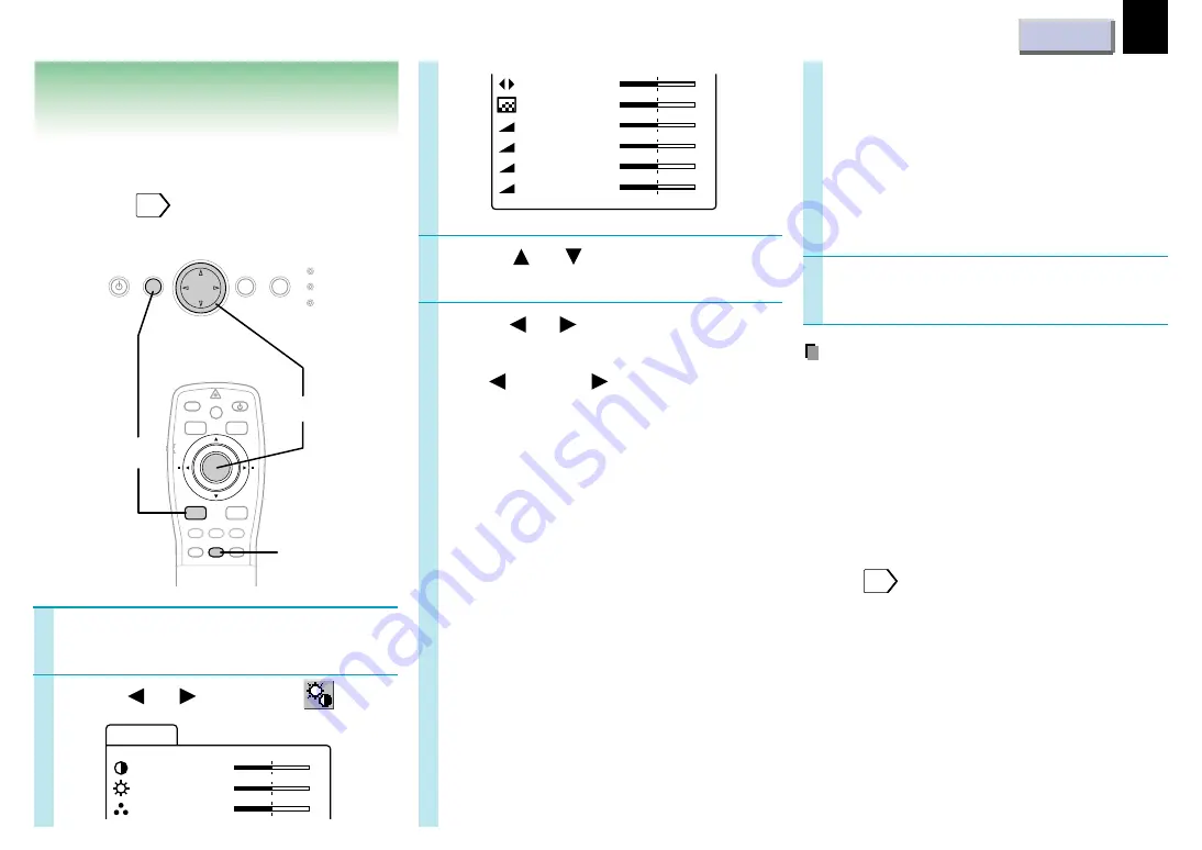
Picture adjustments
– Picture

1

3

2

Press   or   to select a
preferred item.

Press   or   to adjust the item.

To select another item, go back to step 3.

– : 

      + : 

Contrast :

(–) Lower
(+) Higher

Brightness:

(–) Darker
(+) Brighter

Color:

(–) Duller
(+) Brighter

Tint:

(–) Redder
(+) Greener

Sharpness: (–) Softer

(+) Sharper

R-level:

(–) To reduce red
(+) To increase red

G-level:

(–) To reduce green
(+) To increase green

B-level:

(–) To reduce blue
(+) To increase blue

Preparation
• Display the image as explained in “Picture

Projection”

21

• Set the POINTER/PJ selector to “PJ”.

Press MENU to display the
menu.

Press   or   to select 

 .

4

Camera gain: (For document imaging
camera model only)

(–) To lower the camera
sensitivity when the
subject is too bright.
(+) To raise the camera
sensitivity when the
subject is too dark.

Press MENU.

The menu disappears.

Notes

• The adjustment can be stored on each input

source (RGB, Video, Camera).

• Some item may be displayed in gray

depending on an input source. The item
displayed in gray cannot be adjusted and/or
set.

• These adjustments are stored until you turn

the power off.

• To store the adjustments even if the power is

turned off, follow the procedure of “Saving
data”

34

• Pressing RESET will return the adjustment or

setting currently selected to default.

5

AUTO SET

POINTER

PJ

MARKER

LASER

MENU

ENTER

KEYSTONE

ON/STANDBY

R-CLICK

L-CLICK

VIDEO CAMERA

RGB

RESET

FREEZE

RESIZE

RESET

ON/STANDBY

MENU

ENTER

SELECT/ADJUST

INPUT

ON

LAMP

TEMP

1,5

2-4

C o n t r a s t

P i c t u r e

+

B r i g h t n e s s

C o l o r

+

+

T i n t

S h a r p n e s s

+

+

R - l e v e l

+

G - l e v e l

+

B - l e v e l

+

C ame r a g a i n

+

Содержание TLP-681

Страница 1: ...CONTENTS 1 Before use TLP680U TLP681U OWNER S MANUAL WITH DOCUMENT IMAGING CAMERA 3LCD DATA PROJECTOR ...

Страница 2: ...ital device pursuant to part 15 of the FCC Rules These limits are designed to provide reasonable protection against harmful interference when the equipment is operated in a commercial environment This equipment generates uses and can radiates radio frequency energy and if not installed and used in accordance with the instruction manual may cause harmful interference to radio communications Operati...

Страница 3: ...t as it was originally packed at the factory Avoid Volatile Liquid Do not use volatile liquids such as an insect spray near the unit Do not leave rubber or plastic products touching the unit for a long time They will mar the finish Moisture Condensation Never operate this unit immediately after moving it from a cold location to a warm location When the unit is exposed to such a change in temperatu...

Страница 4: ...w all the operating and other instructions 2 Power Sources This product should be operated only from the type of power source indicated on the marking label If you are not sure of the type of power supply to your home consult your product dealer or local power company For products intended to operate from battery power or other sources refer to the operating instructions 3 Source of Light Do not l...

Страница 5: ...leaners Use a damp cloth for cleaning 8 Power Cord Protection Power supply cords should be routed so that they are not likely to be walked on or pinched by items placed upon or against them paying particular attention to cords at plugs convenience receptacles and the point where they exit from the product 9 Overloading Do not overload wall outlets extension cords or integral convenience receptacle...

Страница 6: ...d bottom plates of this product develops heat and may give some undesirable damage to other unit 14 Attachments Do not use attachments not recommended by the product manufacturer as they may cause hazards 15 Accessories Do not place this product on an unstable cart stand tripod bracket or table The product may fall causing serious injury to a child or adult and serious damage to the product Use on...

Страница 7: ...RTANT SAFETY INSTRUCTIONS 17 Servicing Do not attempt to service this product yourself as opening or removing covers may expose you to dangerous voltage or other hazards Refer all servicing to qualified service personnel 18 Replacement Parts When replacement parts are required be sure the service technician has used replacement parts specified by the manufacturer or have the same characteristics a...

Страница 8: ... a thermal paper 23 Do not move the projector while the arm is still erect Always store the arm back in position when moving the projector Otherwise injury or damage may result 24 Do not look into the arm light while it is lit The strong light may cause damage to your eyes or sight 25 If glass components including lens and lamp should break contact your dealer for repair service This product incor...

Страница 9: ...f your line voltage is 220 to 240 use one of the following types of cable Plug type EURO 240V 10 15A UK 240V 6A Australian 240V 10A North American 240V 15A Switzerland 240V 6A Line voltage 220 240V 200 240V 200 240V 200 240V 200 240V Plug configuration ...

Страница 10: ...stments on the menu 27 Initial settings Default 28 Keystone correction Keystone 30 Projection adjustments Image 31 Picture adjustments Picture 32 Sound adjustments Audio 33 Saving data Save 34 Camera Part names and functions of document imaging camera 35 Picture projection with the document imaging camera 37 Overlaying projection 39 Maintenance Trouble indications 40 Air filter lens and main unit ...

Страница 11: ...using ring 21 Infrared remote sensor Intake holes ON STANDBY button 21 To turn the projector on or off MENU button 27 To display or close the menu SELECT ADJUST button 28 To select items or adjust values on the menu ENTER button 30 To enter your selection on the menu INPUT button 21 To select the input source ON indicator 21 40 LAMP indicator 21 40 TEMP indicator 40 Continued 5 8 7 6 1 3 2 4 5 8 7...

Страница 12: ...O output 17 To connect to a monitor or audio equipment RGB INPUT connectors RGB input AUDIO input 16 To connect a computer etc VIDEO INPUT connectors S VIDEO input VIDEO input AUDIO input 17 To connect a video equipment etc Continued Document imaging camera model 1 2 3 4 RS 232C CONTROL RGB AUDIO MONITOR OUTPUT RGB S VIDEO VIDEO VIDEO INPUT L AUDIO R AUDIO RGB INPUT 1 2 3 4 Speaker Infrared remote...

Страница 13: ...er To substitute for the L CLICK button by pressing the center Continued Caution use of controls or adjustments or performance of procedures other than those specified herein may result in hazardous radiation exposure 4 5 3 2 1 Laser emission part 17 16 15 14 13 12 11 10 9 1 2 3 4 5 6 7 8 AUTO SET POINTER PJ MARKER LASER MENU ENTER KEYSTONE ON STANDBY R CLICK L CLICK VIDEO CAMERA RGB RESET FREEZE ...

Страница 14: ... the screen R CLICK button 26 ENTER button 30 To right click To enter your selection on the menu VIDEO button 21 To select the video input CAMERA button for document imaging camera model only 37 To select the camera input RESET button 29 To restore the settings and adjustments to the default FREEZE button 23 To freeze the picture 6 7 8 14 13 12 11 10 9 15 MUTE button 23 To cut off the picture and ...

Страница 15: ...rcumstances the remote control may not operate well due to the location being used or the surroundings At such times change the direction of the remote control to the projector and retry the operation Rear side document imaging camera model Rear side Front side Notes Using batteries incorrectly can cause them to leak or burst Strictly observe the following Install the batteries with their and ends...

Страница 16: ...jector cannot be connected to a computer that does not have an analog RGB output terminal For details refer to the computer manual You may not be able to connect some computers to the projector For details consult the dealer The adapter for Macintosh computers is conformable to MULTIPLE SCAN 21 Continued RS 232C CONTROL RGB AUDIO MONITOR OUTPUT RGB S VIDEO VIDEO VIDEO INPUT L AUDIO R AUDIO RGB INP...

Страница 17: ...system etc The MONITOR OUTPUT RGB output connector always sends out a signal which is input to the RGB INPUT RGB input connector regardless of your source selection Even while the projector is in standby mode the MONITOR OUTPUT RGB output connector continues its output Note Signal input to the S VIDEO jack takes priority over that to the VIDEO jack RS 232C CONTROL RGB AUDIO MONITOR OUTPUT RGB S VI...

Страница 18: ...he front of the screen from a floor Floor mounted rear projection Viewing a picture projected through the back of the screen from a floor installation Ceiling mounted front projection The document imaging camera model could not be mounted on the ceiling Viewing a picture projected on the front of the screen from a ceiling installation Ceiling mounted rear projection The document imaging camera mod...

Страница 19: ...istance between the lens and the screen The projection size depends on the distance between the lens and the screen Adjust the projection size by changing the distances as shown below 2 Screen size inches 23 40 60 80 100 150 200 250 b cm 4 6 9 12 15 23 30 38 Minimum WIDE 1 56 2 373 3 186 3 999 6 031 8 064 10 096 Maximum TELE 1 132 2 017 3 059 4 1 5 142 7 746 10 35 a m Connect the power cord Insert...

Страница 20: ...distorted If the projector is tilted the picture may be distorted To obtain the best possible picture place the projector so it faces the screen squarely Continued How to use the foot adjuster The tilt of the projector can be adjusted using the foot adjuster 1 Lift the front of the projector until a tilt angle desired is obtained and hold down the foot adjuster release button The foot adjuster wil...

Страница 21: ...on the screen changes as follows RGB To project pictures from a computer connected to RGB INPUT Video To project pictures from a video player connected to VIDEO INPUT Camera To project pictures from a document imaging camera For document imaging camera model only Adjust the picture size by turning the zooming ring Turn to the right to enlarge the picture Turn to the left to reduce the picture Focu...

Страница 22: ...The ON idicator lights in orange 3 After confirming the exhaust fan stops unplug the power cord The ON indicator turns off Continued Continued Notes Even after turning the power off the intake and exhaust fans continue to work for a while to cool the inside of the projector Immediately after the power off the projector may not be turned on while the LAMP indicator is flashing in green Before unplu...

Страница 23: ...y other operations can also release the picture Note This function is convenient for the case where you are using the document imaging camera model and change documents to project through the camera Displaying the input source information Press CALL The current input source and the signal status information is displayed To close the display press CALL again Note If you press CALL while the menu is...

Страница 24: ...ightward When the picture size is larger than the projection area To view the upper side of the picture To view the lower side of the picture To view the left side of the picture To view the right side of the picture Notes Picture size returns to normal after the power is turned off The values are not saved You may not change the picture size depending to the signal Pictures of VGA signals etc may...

Страница 25: ...uter use the supplied PS 2 mouse adapter if you are using a PS 2 mouse or connect the supplied IBM MAC cable directly to your computer if you are using a serial mouse When connecting the REMOTE MOUSE RECEIVER to the USB PORT for the first time insert the Windows98 CD ROM and install the device drivers for a USB interchangeability device and a USB human interface devices two kinds The installation ...

Страница 26: ... right click Press R CLICK To drag and drop While holding down the center of the pointer control press the rim and release the center Notes The remote control operating range is about 5 meter from the front of the remote sensor The remote control may not operate when there is sunlight or other strong light such as a fluorescent lamp shining on the remote sensor AUTO SET POINTER PJ MARKER LASER MEN...

Страница 27: ...To adjust the color depth Tint To adjust the tint Sharpness To adjust the sharpness R level To adjust the amount of red in the picture G level To adjust the amount of green in the picture B level To adjust the amount of blue in the picture Camera gain To adjust the sensitivity of the document imaging camera For document imaging camera model only Audio Volume To adjust the sound volume of the speak...

Страница 28: ...al type of the source from the followings NTSC M NTSC M signal NTSC443A NTSC4 43A signal NTSC J NTSC J signal NTSC N NTSC N signal NTSC443B NTSC4 43B signal PAL PAL signal PAL N PAL N signal SECAM SECAM signal PAL443 PAL4 43 signal PAL M PAL M signal 2 Continued Press or to select Press or to select a preferred item Press or to make the setting To select another item go back to step 3 Language Sel...

Страница 29: ...appear Off On screen displays do not appear Press MENU The menu disappears Notes These settings are stored until you turn the power off To store the settings even if the power is turned off follow the procedure of Saving data 34 Pressing RESET will return the adjustment or setting currently selected to default Continued 5 ...

Страница 30: ... 2 On the menu select Auto set in Keystone 3 Press RESET Notes Do not make the 0 degrees setting on an inclined or unstable surface or in a shaky place as it may not be performed properly To store this setting even if the power is turned off follow the procedure of Saving data 34 Preparation Display the image as explained in Picture Projection 21 Set the POINTER PJ selector to PJ Press MENU to dis...

Страница 31: ...the image may not be projected properly depending on the computer model In this case turn off the computer display or make the necessary picture adjustments on the projector For details on controlling the computer display etc refer to the computer s manual and description on the software for the computer used During adjustments of H position or V position the image may not be projected properly Wh...

Страница 32: ...too bright To raise the camera sensitivity when the subject is too dark Press MENU The menu disappears Notes The adjustment can be stored on each input source RGB Video Camera Some item may be displayed in gray depending on an input source The item displayed in gray cannot be adjusted and or set These adjustments are stored until you turn the power off To store the adjustments even if the power is...

Страница 33: ... the POINTER PJ selector to PJ Press MENU to display the menu Press or to select Press or to select a preferred item Press or to adjust the item To select another item go back to step 3 Volume To turn down To turn up Bass To reduce the bass To increase the bass Treble To reduce the treble To increase the treble Press MENU The menu disappears 4 5 AUTO SET POINTER PJ MARKER LASER MENU ENTER KEYSTONE...

Страница 34: ...preferred item Save data To save the adjustments and settings on the menu All preset To restore the adjustments and settings on the menu to the factory set Press ENTER Press MENU The menu disappears 4 5 Sa v e d a t Save a A l l p r e s e t AUTO SET POINTER PJ MARKER LASER MENU KEYSTONE ON STANDBY L CLICK VIDEO CAMERA RGB RESIZE ON STANDBY MENU ENTER SELECT ADJUST INPUT ON LAMP TEMP FREEZE RESET E...

Страница 35: ...irectly project any materials documents illustrations etc without using an OHP film Camera head Arm OVERLAY button 39 To activate the overlaying projection PHOTO TEXT button 38 To switch modes between text and photo ARM LIGHT button 37 To turn on or off the light LOCK W BALANCE indicator 38 Lights when the white balance is locked W BALANCE button 38 To switch white balance settings between automat...

Страница 36: ...e arm 2 Stretch the arm 3 Turn the arm 4 Open the camera head 5 Turn the camera head 6 Pull up the light 7 Turn the light Notes Never give shocks or impacts to the camera or arm as this may cause breakdowns While raising up the arm in step 2 be careful not to hit your face or your body ...

Страница 37: ... the camera control panel or INPUT on the main unit can also select it Camera is displayed Move the camera head to adjust the size of the picture You can project around the projector by moving the arm and the camera head 2 1 3 Continued Up To reduce Down To enlarge 4 AUTO SET POINTER PJ MARKER LASER MENU ENTER KEYSTONE ON STANDBY R CLICK L CLICK VIDEO CAMERA RGB RESET FREEZE RESIZE ON STANDBY MENU...

Страница 38: ...to turn the LOCK indicator off Notes If you raise up the arm while the camera input is selected the color of the picture may vary for an instant due to the white balance adjustment This is not malfunction If you put back the arm and raise it up while the white balance is locked the LOCK indicator is lit the projector releases the white balance but leaves the LOCK indicator on In this case press W ...

Страница 39: ...on Press OVERLAY The camera source is overlaid on the picture Project the paper using the camera Write on the paper with a blue or red pen The handwriting is superimposed on the picture Notes Handwriting in colors except blue and red cannot be displayed properly Handwriting in fine lines may not be displayed properly When Y Pb Pr signal enters the overlaying projection function is not available 4 ...

Страница 40: ...ome on The inside is too hot or the projector has been working in an area of high temperature Place the projector correctly so the intake and exhaust fans holes are not covered Turn the projector off and leave it for a while and turn it on again Clean the air filter 41 ON Lit red LAMP TEMP Flashing red The power turns off or does not come on Trouble with the intake fan Unplug the power cord and ca...

Страница 41: ...the air filter is dusty the ventilation is impaired This causes the temperature inside the projector to rise and may damage the unit Attach the air filter cover firmly after the cleaning If it is not set correctly the dusts will enter and they will be projected and overlapped on the picture Cleaning the lens Use a blower or a lens cleaner to clean the lens Never rub or tap the lens with a hard obj...

Страница 42: ... the power cord Wait until the lamp gets cold enough 3 Take off the lamp cover on the bottom panel Loosen two screws and pull off the lamp cover Pull out the lamp Loosen the two fixing screws and lift up the handle to pull out the lamp Load a new lamp Slide until it hits the bottom and tighten the two fixed screws Attach the lamp cover Slide the cover in place and tighten two screws Reset the lamp...

Страница 43: ...elected Select the input source correctly 21 The audio muting mode is on Press MUTE to restore the sound 23 The sound volume is at the minimum Adjust the sound volume on the menu 33 The source is not correctly connected to the projector Connect the source correctly to the projector 16 The images are blurred Focusing is uneven The lens is dirty Clean the lens Use a lens cleaner to clean the lens 41...

Страница 44: ...picture by turning the focusing ring 21 The light is not on The image may not be projected clearly if the light is not on Turn on the light 37 The remote control does not work The remote control is not facing the remote sensor Face the remote control transmitter toward the remote sensor on the projector 15 The remote control is too far Operate within about 5 meters 15 There is an obstruction betwe...

Страница 45: ...40 640 640 800 800 800 800 800 832 1024 59 940 50 000 60 000 60 000 60 000 60 000 56 420 70 090 70 090 85 080 85 080 59 940 72 809 75 000 85 008 66 667 56 250 60 317 72 188 75 000 85 061 74 550 43 479x2 484 574 480 480 720 1080 400 350 400 350 400 480 480 480 480 480 600 600 600 600 600 624 768 N N N N N N N N N N N N N N P N N P P N N P N N N N N N N N P P P P P P P P P P P P NTSC PAL SECAM NTSC ...

Страница 46: ... 65 000 70 000 75 000 1024 1024 1024 1024 1024 1152 1152 1280 1280 1280 1280 1280 1280 1600 1600 1600 1600 768 768 768 768 768 864 870 960 960 1024 1024 1024 1024 1200 1200 1200 1200 N N N N P P N N N N P P P P P P P P P P P P P P P P P P P P P P RGB IN RGB IN RGB IN RGB IN RGB IN RGB IN RGB IN RGB IN RGB IN RGB IN RGB IN RGB IN RGB IN RGB IN RGB IN RGB IN RGB IN Notes If the mode identification d...

Страница 47: ...arity Vertical synchronizing signal TTL level positive negative polarity Composite synchronizing signal TTL level Pin arrangements Pin No 1 2 3 4 5 6 7 8 9 10 11 12 13 14 15 Video input Red Video input Green Video input Blue N C GND GND Red GND Green GND Blue N C GND GND N C Horizontal synchronizing composite synchronizing signal Vertical synchronizing signal N C Continued 5 1 6 11 15 10 ...

Страница 48: ... 56 64 24 40 56 16 32 40 24 24 16 48 20 64 96 96 64 64 96 40 64 56 64 72 128 120 80 64 64 136 136 96 96 96 848 800 800 832 832 800 832 840 832 864 1024 1056 1040 1056 1048 1152 1344 1328 1312 1376 1320 24 83 31 47 31 47 37 86 37 86 31 47 37 86 37 50 43 27 35 00 35 16 37 88 48 08 46 88 53 67 49 72 48 363 56 476 60 023 68 677 60 197 56 42 70 09 70 09 85 08 85 08 59 94 72 81 75 00 85 01 66 67 56 25 6...

Страница 49: ...ut Video Input Camera Resize reset Resize 1 Resize 2 Resize 3 Resize 4 Automatic W B OFF Automatic W B ON Text mode OFF Text mode ON Overlaying mode OFF Overlaying mode ON Adjustment value reset Adjustment value increase 7 6 3 4 1 2 5 8 RS 232C 9600 bps No parity Data length 8 bit Stop bit 1 bit STX 02h Command 3Byte ETX 03h One command only can be used in one communication Command shall be compos...

Страница 50: ...tting English display setting French display setting Classification Default Default Default Default Default Default Default Default Default Default Default Default Default Default Default Default Default Default Default Default Default Default Default Save Save Command LGR LIT LSP LP0 PJ0 PJ1 PJ2 PJ3 KR0 KR1 KV0 KV1 KV2 KV3 KV4 KV5 KV6 KV7 KV8 KV9 KVA MO0 MO1 DRS DSV Meaning German display setting...

Страница 51: ...al 1V p p 75Ω Audio 1V p p more than 22kΩ RCA pin jack MONITOR OUTPUT RGB signal D sub 15 pin Audio 1V p p less than 2 2kΩ ø3 5mm stereo mini jack CONTROL terminal Mini DIN 8 pin RS 232C Cabinet Material ABS resin Liquid crystal display Projection system 3 pannels transmission Panel size 0 9 inches Driving system TFT active matrix Picture elements TLP680U TLP681U 786 432 pixels 1024 x 768 dots x 3...

Страница 52: ... MAC mouse adapter for REMOTE MOUSE RECEIVER 1 USB mouse cable for REMOTE MOUSE RECEIVER 1 Carrying case 1 The design and specifications are subject to change without notice Trademarks NEC PC 98 series are trademarks of NEC Corporation IBM DOS V VGA SVGA XGA SXGA UXGA are trademarks or registered trademarks of International Business Machines Corporation Macintosh is a registered trademark of Apple...

Страница 53: ...or workmanship as limited above and do not extend to any product or parts which have been lost or discarded by you or to damage to products or parts caused by misuse accident improper installation improper maintenance or use in violation of instructions furnished by us or to units which have been altered or modified without authorized of TACP or to damage to product or parts thereof which have had...

Страница 54: ...ing 7 If you have any questions about service please contact the following TACP Service Center TACP is not obligated to provide purchasers with a substitute unit during the warranty period 82 Totowa Rd Wayne NJ 07470 U S A Phone 973 628 8000 Fax 973 628 1875 Toll Free for Service Call 1 800 631 3811 Continued ...

Отзывы: