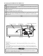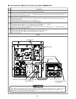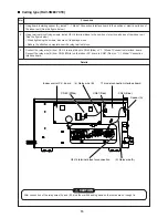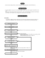
22
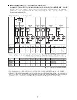
Address Setup/Change Method
4, 7, 10
14
2, 12, 13
5, 8, 11
1
3, 6, 9
TEMP.
ON / OFF
SET
TIME
TEST
FILTER
RESET
CL
SAVE
SWING/FIX
VENT
UNIT LOUVER
CODE No.
R.C.
No.
TIMER SET
MODE
FAN
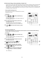
<Procedure>
1
Push
SET
,
CL
and
TEST
buttons
simultaneously for 4 seconds or more.
LCD changes to flashing.
(The firstly displayed unit No. is the header indoor unit No. in the group control.)
2
In group control, use
UNIT LOUVER
button (left side of the button) for change.
Select the indoor unit No. (The fan of the selected indoor unit is turned on.)
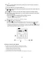
<Line address>
3
Using the setup temperature
and
buttons, select CODE No. “12”.
4
Using timer time
and
buttons, set up the line address.
5
Push
SET
button.
(OK when display goes on.)
<Indoor unit address>
6
Using the setup temperature
and
buttons, select CODE No. “13”.
7
Using timer time
and
buttons, set up
the indoor unit address.
8
Push
SET
button.
(OK when display goes on.)
<Group address>
9
Using the setup temperature
and
buttons, select CODE No. “14”.
10
Using timer time
and
buttons, set up Individual
= 0000, Header unit = 0001, and Follower unit = 0002.
11
Push
SET
button. (OK when display goes on.)
12
Using
UNIT LOUVER
button (left side of the button), select an indoor unit No. to be changed at the next
time.
Repeat procedure from
3
to
12
and change setup so that addresses are not overlapped.
13
After the above change, push
UNIT LOUVER
button (left side of the button) to check the changed contents.
14
If all is right, push
TEST
button. Setup ends.
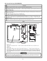
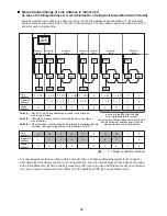
Outdoor
#1
Indoor Indoor Indoor
Outdoor
#2
Indoor Indoor
1
2
2
1
3
2
2
1
2
2
2
2
Follower unit
Header unit
Line address
→
1
Indoor unit address
→
1
Group address
→
1
Remote
controller
<Wiring example of 2 lines>
⎫
⎬
⎭
Group address
Individual
: 0000
Header unit : 0001
In case of group control
Follower unit : 0002

