


4-14
T2150 Series
4.
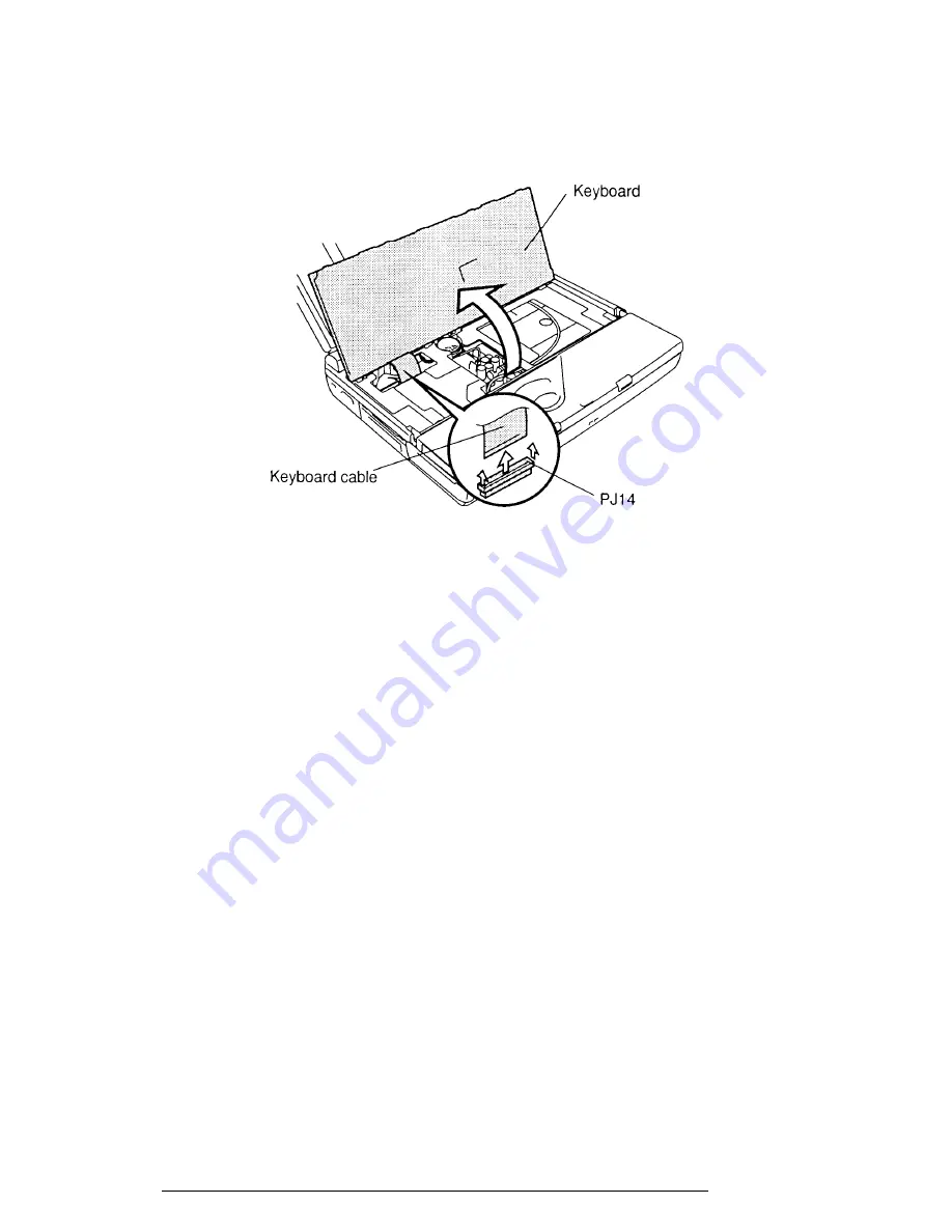
Carefully lift the
keyboard
to expose the
keyboard connector
(figure 4-11).
5.
Disconnect the
keyboard cable
from the
pressure-plate connector (PJ14)
on the
system board (figure 4-11).
Figure 4-11 Removing the keyboard
Installing the Keyboard
To install the T2150 series keyboard, follow the steps below and refer to figures 4-10 and
4-11.
1.
Connect the keyboard cable to the pressure plate connector (PJ14) on the
system board (figure 4-11).
2.
Replace the keyboard. Fit notches on the back of the keyboard into corre-
sponding holes on the computer and lay the keyboard in place (figure 4-11).
3.
Insert the keyboard brace between the AccuPoint cable and the underside of
the keyboard (figure 4-10).
4.
Secure the five latches on the keyboard base (figure 4-10).
5.
Install the optional PCMCIA card, optional memory module, and battery pack
as described in sections 4.2 through 4.4.
Содержание T2150 series
Страница 22: ...T2150 Series 2 3 Figure 2 1 Troubleshooting flowchart 1 2 ...
Страница 135: ...4 20 T2150 Series Figure 4 17 Removing the top cover display assembly ...
Страница 162: ...T2150 Series B 1 Appendix B Board Layout B 1 FHVSY System Board Figure B 1 FHVSY system board front ...
Страница 163: ...B 2 T2150 Series Figure B 2 FHVSY system board back ...
Страница 164: ...T2150 Series B 3 B 2 FHWSD Board Figure B 3 FHWSD board ...
Страница 181: ...C 14 T2150 Series ...
Страница 182: ...T2150 Series D 1 Appendix D USA Display Codes Table D 1 USA display codes ...
Страница 190: ...F 2 T2150 Series F 3 German GR Keyboard Figure F 3 GR keyboard F 4 French FR Keyboard Figure F 4 FR keyboard ...
Страница 191: ...T2150 Series F 3 F 5 Spanish SP Keyboard Figure F 5 SP keyboard F 6 Italian IT Keyboard Figure F 6 IT keyboard ...


