ISDN Interfaces
10-14
Strata CT I&M Manual October 2000
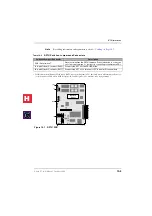
Step 3: Install the RBSS
Note
If one or two additional BRI-NT circuits are required, install the RBSS (see
1.
Align the four connectors carefully while observing the “UP” arrows on the REBS1A.
2.
Plug the RBSS onto the RBSU.
Step 4: Install the R40S1A
Note
If the TA demands power from the BUS, install the R40S (optional PCB) (see
1.
Align the two connectors carefully while observing the “UP” arrows on the R40S1A.
2.
Plug the R40S1A onto the RBSU.
Figure 10-9
Location of RBSU Plug-on PCBs
Step 5: Install RBSU/RBSS PCBs into Cabinet
After setting the switches and jumpers and installing the plug-on PCBs as described in the
preceding paragraphs, the RBSU/RBSS PCBs can be installed in the appropriate cabinet
slots. After the RBSU/RBSS is installed in the Strata CT cabinet, the status LEDs and
connecting jacks are positioned as shown in
UP
UP
UP
UP
UP
UP
R40S1A-CM V.1
RBSU
Optional RBSS1A
REBU
R40S1A
2761
(pre installed on RBSU1 -
not used on RBSU2)
Optional PS-1 Power Supply
Two-circuit Subassembly
H
C
Содержание Strata CT
Страница 36: ...Strata CT Configuration 1 22 Strata CT I M Manual October 2000 H C ...
Страница 94: ...Strata CT Installation 2 58 Strata CT I M Manual October 2000 H C ...
Страница 242: ...Peripheral Installation 6 54 Strata CT I M Manual October 2000 H C ...
Страница 258: ...ACD Installation 7 16 Strata CT I M Manual October 2000 H C ...
Страница 274: ...Fault Finding 8 16 Strata CT I M Manual October 2000 H C ...
Страница 326: ...Computer Telephony Integration Handling Incoming Calls 9 52 Strata CT I M Manual October 2000 H C ...
Страница 364: ...ISDN Interfaces 10 38 Strata CT I M Manual October 2000 H C ...
Страница 370: ...Notes to Users A 6 Strata CT I M Manual October 2000 H C ...


