background image

10. SPECIFICATIONS


EO1-12028 


10.1 Basic Specifications


10- 2 


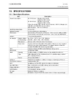
Item Description 

Display type 

12.1-inch color TFT with touch panel 

Display size 

12.1-inch 800 x 600 dots 

Number of colors 

64K color (65,536 colors) 

Brightness 300 

cd 

Display area 

246 mm (W) x 184.5 mm (H) 

Dot size 

0.3075 mm (W) x 0.3075 mm (H) 

Touch panel 

Analog Resistor Film (1024 x 1024 dots) 

Operator’s 
Display 

Adjustment 
mechanism 

Brightness volume (TFT) and Tilt angle (Free adjustment in a range of 
15

°

 to 55

°

No swivel adjustment 

Number of displayed 
characters 

5 x 7 dot fluorescent display 20 digits x 2 lines 
20 triangles under the 2nd line 

Display color 

Blue 

Display 
area/character size 

Character size: 5.5 mm (W) x 10.5 mm (H) 
Character pitch: 7.4 mm (W) x 15.5 mm (H) 

Type font 

182 types of half width ANK 

Display angle 

(NOTE)


Tilt: 10

°

 to 42

°


Swivel: 0

°

 to 90

°

 (in both directions) 

BIU 
(Option) 

Interface with 
ENGINE 

RS-232C interface 

NOTE:  The swivel angle of the BIU varies according to the tilt angle of the operator’s display. 


Tilt angle of the operator’s display 

Tilt angle of the BIU 

Swivel angle of the BIU 

10

°

 90

°

 (6 steps, both directions) 

15

°


42

°

 90

°

 (6 steps, both directions) 

10

°

 45

°

 (3 steps, both directions) 

55

°


42

°

 30

°

 (2 steps, both directions) 


Содержание ST-70 SERIES

Страница 1: ...Owner s Manual ST 70 SERIES ...

Страница 2: ...pursuant to Part 15 of the FCC Rules These limits are designed to provide reasonable protection against harmful interference when the equipment is operated in a commercial environment This equipment generates uses and can radiate radio frequency energy and if not installed and used in accordance with the instruction manual may cause harmful interference to radio communications Operation of this eq...

Страница 3: ...ating plate as this may cause fire or electric shock If the machines share the same outlet with any other electrical appliances that consume large amounts of power the voltage will fluctuate widely each time these appliances operate Be sure to provide an exclusive outlet for the machine as this may cause fire or electric shock Do not place metal objects or water filled containers such as flower va...

Страница 4: ...ner or other volatile solvent for cleaning At the end of the day turn the power OFF then clean and inspect the exterior of the machine Try to avoid using this equipment on the same power supply as high voltage equipment or equipment likely to cause mains interference USE ONLY TOSHIBA TEC SPECIFIED consumables DO NOT STORE the consumables where they might be exposed to direct sunlight high temperat...

Страница 5: ...Disk 6 1 6 2 Ejecting A Floppy Disk 6 1 7 MAGNETIC CARD READER OPTION 7 1 7 1 How to Read Magnetic Card 7 1 8 GENERAL MAINTENANCE 8 1 8 1 Cleaning 8 1 9 TROUBLESHOOTING 9 1 10 SPECIFICATIONS 10 1 10 1 Basic Specifications 10 1 10 2 Options 10 3 CAUTION 1 This manual may not be copied in whole or in part without prior written permission of TOSHIBA TEC 2 The contents of this manual may be changed wi...

Страница 6: ...efully to help gain maximum performance and life from your POS terminal For most queries please refer to this manual and keep it safe for future reference 1 1 Accessories Confirm that all the following accessories are contained in the carton If any accessories are missing or damaged contact your TOSHIBA TEC service representative Owner s Manual 1 copy AC Adapter 1 pc Cable Clamp 2 pcs Ferrite Core...

Страница 7: ...ont View 2 1 2 APPEARANCE 2 1 Front View 2 2 Rear View PC Card Cover USB Cover Speaker BIU Option Memory Cover 12 1 TFT Color Display with Touch Panel MCR Unit Option FDD Unit Option HDD Cover Power LED Green HDD LED Yellow Speaker ...

Страница 8: ...the display panel or the portion where the CPU touches It becomes hot around the Memory Cover and CPU so care must be taken not to touch there continuously This POS terminal is not provided with a cooling fan for the CPU Instead the rear cover of the display panel is made of aluminium die cast which allows heat to cool The aluminium cover becomes hot during operation but this is not machine failur...

Страница 9: ...ED type LED status LAN status ON OFF Linked Unlinked LINK ACT Blink Frame is sent received Off 10M SPEED On 100M USB 3 Connector for the USB Universal Serial Bus interface USB V2 0 1 1 and UHCI conforming to Universal Hub Controller Interface V2 0 1 1 NOTE USB functions may not be supported depending on the Operating System PC Card Interface Slot This complies with PC Card Standard Release 8 0 32 ...

Страница 10: ...ectable LPT1 D sub 25 pin female connector Printer etc having a Centronics interface or equivalent are connectable LAN Modular type connector for the 10BASE T 100BASE TX LAN interface USB1 2 Connector for the USB Universal Serial Bus interface USB V2 0 1 1 and UHCI conforming to Universal Hub Controller Interface V2 0 1 1 NOTE USB functions may not be supported depending on the Operating System PS...

Страница 11: ... 1 Loosen the screws on the bottom of the terminal to remove the Front Cover 2 Connect the Power Cord to the AC adapter NOTE The EA10953A1 AC adapter should be exclusively used for the ST 70 Series POS Terminal The ST 70 Series POS Terminal must be powered by the EA10953A1 AC adapter Front Cover Screw AC Adapter Power Cord ...

Страница 12: ...ect the AC Adapter Plug When unplugging the AC adapter be sure to hold the shell portion by fingers Since the plug of the AC adapter is provided with a lock mechanism The plug is unlocked by pulling the shell backward CAUTION When unplugging the AC adapter do not pull the cord potion Doing so may cut the internal wire or damage the plug ...

Страница 13: ...e AC Adapter 4 3 4 Hook the upper side of the Front Cover on the POS terminal and then tighten the screw to secure the Front Cover 5 Insert the Power Cord plug into the AC Outlet The LED on the AC Adapter will lights in green Screw Hook Front Cover Hook ...

Страница 14: ...ional BIU is also adjustable in a range of 10 to 42 5 2 Brightness Adjustment The brightness control is provided on the lower left of the operator s display inside the power switch cover Use a jeweler s screw driver to turn the brightness control Clockwise turn makes the display darker and counterclockwise turn makes it brighter CAUTION Do not adjust the display angle by holding the LCD panel Doin...

Страница 15: ... the POS terminal CAUTION Do not press the eject button while the active LED is lit Doing so may destroy the data in the floppy disk Active LED Eject Button BIU Floppy Disk Drive CAUTION 1 When using the floppy disk drive on the ST 70 with a BIU do not place it behind the BIU Doing this may cause a malfunction of the floppy disk drive Be sure to place the floppy disk drive on a flat and stable sur...

Страница 16: ...etic card reader can be installed on the right side of this POS terminal 7 1 How to Read Magnetic Card Insert the magnetic card into the upper portion of the magnetic card reader slot and slowly move the card downward NOTE Moving the magnetic card too fast or too slowly may cause a read error Magnetic Card MCR Unit Option ...

Страница 17: ...tly moistened with mild detergent After using detergent for cleaning be sure to wipe it off with a slightly moistened cloth CAUTION 1 Never use an organic solvent like thinners or benzene for cleaning Using such solvents may discolor the covers 2 Do not use any sharp object to clean the operator s display Doing so may cause an operator s display failure 3 Do not insert the nozzle of an air blower ...

Страница 18: ...annot be used Is the floppy disk drive connected properly Turn OFF the POS terminal and then connect the floppy disk drive again Any data cannot be written into the floppy disk Is the floppy disk write protected Is the floppy disk formatted properly Is the memory insufficient Eject the floppy disk and cancel the write protect Format the floppy disk properly Delete unnecessary data or prepare a new...

Страница 19: ...33 0 mm D x 33 5 mm H AC adapter Power cord A power cord is not included in this product Please use one complied with each country s safety standard For details please contact the nearest TOSHIBA TEC service representative CPU Intel ULV Celeron 650MHz with 256KB secondary cache BIOS ROM 512KB Flash ROM Capacity 512MB 256MB or 128MB memory can be installed in each slot Type DDR SDRAM PC2100 133MHz ...

Страница 20: ...r of displayed characters 5 x 7 dot fluorescent display 20 digits x 2 lines 20 triangles under the 2nd line Display color Blue Display area character size Character size 5 5 mm W x 10 5 mm H Character pitch 7 4 mm W x 15 5 mm H Type font 182 types of half width ANK Display angle NOTE Tilt 10 to 42 Swivel 0 to 90 in both directions BIU Option Interface with ENGINE RS 232C interface NOTE The swivel ...

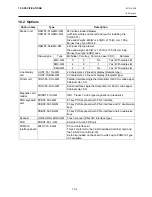
Страница 21: ...rs x 2 lines dot display Integrated type TRST 56 P 1G QM Parallel interface single thermal printer for 80 mm wide paper Cabinet color SG Printer unit TRST 56 S 1G QM Serial interface single thermal printer for 80 mm wide paper Cabinet color SG Magnetic card reader MCRST 70 3 QM ISO1 Tracks 1 and 2 type magnetic card reader kit PKBST 50 3 QM 81 key POS keyboard with PS 2 interface PKBST 50 3D QM 81...

Страница 22: ...E PRINTED IN JAPAN EO1 12028B 7LA00486200 ...

Отзывы: