40
Function setup
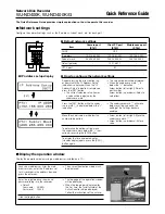
TV Shape
DVD
4:3 Letterbox:
Select when a standard 4:3 TV is
connected.
Displays theatrical images with
masking bars above and below the
picture.
4:3 Normal:
Select when a standard 4:3 TV is
connected.
Displays pictures cropped to fill
your TV screen. Either or both
sides of the picture are cut off.
16:9 Widescreen: Select when a 16:9 wide TV is
connected.
Notes
• The displayable picture size is preset on the DVD video
disc. Therefore, the playback picture of some DVD
video discs may not conform to the picture size you
select.
• When you play DVD video discs recorded in the 4:3
picture size only, the playback picture always appears
in the 4:3 picture size regardless of the TV shape
setting.
• If you select “16:9 Widescreen” and you own a 4:3 TV
set, the DVD playback picture will be horizontally
distorted during playback. Images will appear to be
horizontally compressed. Always be sure that your TV
shape conforms to the actual TV in use.
PAL/Auto
DVD
PAL: To play a PAL disc. Connect a PAL TV to view a
picture.
Auto: The DVD video player automatically identifies
PAL or NTSC video system of a disc. Connect
a multisystem TV (PAL/NTSC compatible) to
view a picture.
A playback picture may be distorted when
detected a signal change between PAL and
NTSC on the disc.
Setting details
Customizing the Function Settings (continued)
Picture
TV Shape
4:3 LB
AB C
PAL/Auto
Video Out Select
PAL
Video
Video Out Select
DVD
Video:
Select when connected to a normal TV.
16
S Video: Select when connected to a TV compatible
with S video signals.
16
17
RGB:
Select when connected to an RGB monitor.
16
Notes
• When you connect a TV equipped with the component
video inputs, select “Video” or “S Video”.
16
• If the on-screen display disappears immediately after
you select “RGB”, you can restore it by connecting the
DVD player using the VIDEO OUT (yellow) jack.
Содержание SD-110EB
Страница 4: ...SECTION 1 GENERAL DESCRIPTIONS 1 OPERATING INSTRUCTIONS SD 110EB SECTION 1 GENERAL DESCRIPTIONS ...
Страница 80: ...4 2 Power Supply Block Diagram Fig 3 4 2 ...
Страница 82: ...Fig 3 4 5 4 3 3 Front Display Power Switch Block Diagram ...
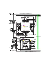
Страница 83: ...µ Fig 3 4 6 4 4 Main Block Diagrams 4 4 1 Servo System Block Diagram ...
Страница 84: ...Fig 3 4 7 4 4 2 Signal System Block Diagram ...
Страница 85: ...Fig 3 4 8 4 5 Output RGB Block Diagram ...
Страница 86: ...10 1 3 4 A B C D E G 2 5 6 7 8 9 F Fig 3 5 1 5 CIRCUIT DIAGRAMS 5 1 Power Supply Circuit Diagram ...
Страница 88: ...10 1 3 4 A B C D E G 2 5 6 7 8 9 F Fig 3 5 3 5 2 Front Display Power Switch Circuit Diagram ...
Страница 91: ...5 3 2 Main Circuit Diagram Fig 3 5 5 ...
Страница 92: ...5 3 2 Main Circuit Diagram ...
Страница 93: ......
Страница 94: ......
Страница 95: ......
Страница 96: ......
Страница 97: ......
Страница 98: ......
Страница 99: ...Fig 3 5 5 ...
Страница 101: ...10 1 3 4 A B C D E G 2 5 6 7 8 9 F Fig 3 5 7 5 4 Output RGB Circuit Diagram ...
Страница 102: ...10 1 3 4 A B C D E G 2 5 6 7 8 9 F 5 5 Motor System Circuit Diagram Fig 3 5 8 ...
Страница 120: ......


