Replacement Procedures
4
4.9 Display assembly
Removing the display assembly
The following describes the procedure for removing the display assembly (See Figure 4-13 to
4-17).
1.
Close the display and turn the computer upside down.
2.
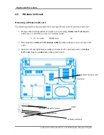
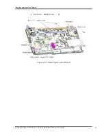
Open the MINIPCI Door and remove the wireless LAN screws and antenna connector.
M2.0x3.0 FLAT BIND
(Locktight)
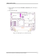
Figure 4-13 Removing the screws (securing display assembly)
4-28
Satellite U300 and Satellite Pro U300 Maintenance Manual (960-Q08)
Содержание Satellite Pro U300
Страница 13: ...Satellite U300 and Satellite Pro U300 Maintenance Manual 960 Q08 13 ...
Страница 14: ...Chapter 1 Hardware Overview ...
Страница 48: ...2 1 CONFIDENTIAL Chapter 2 Troubleshooting Procedures ...
Страница 49: ...2 2 CONFIDENTIAL Satellite U300 and Satellite Pro U300 Maintenance Manual 960 Q08 2 ...
Страница 118: ...Test Program for Field Satellite U300 and Satellite Pro U300 Tests and Diagnostics Manual 17 ...
Страница 171: ...Satellite U300 and Satellite Pro U300 Maintenance Manual 960 Q08 4 i Chapter 4 Replacement Procedures ...
Страница 172: ...Replacement Procedures 4 iiSatellite U300 and Satellite Pro U300 Maintenance Manual 960 Q08 ...
Страница 228: ...Satellite U300 and Satellite Pro U300 Maintenance Manual 960 Q08 App i Appendices ...
Страница 229: ...App ii Satellite U300 and Satellite Pro U300 Maintenance Manual 960 Q08 ...
Страница 239: ...Handling the LCD Module A 6 Satellite U300 and Satellite Pro U300 Maintenance Manual 960 Q08 ...
Страница 241: ...Board Layout Figure B 2 System board layout Back B 2 Satellite U300 and Satellite Pro U300 Maintenance Manual 960 Q08 ...
Страница 285: ...Display codes D 2 Satellite U300 and Satellite Pro U300 Maintenance Manual 960 Q08 ...
Страница 307: ...Wiring Diagrams F 2 Satellite U300 and Satellite Pro U300 Maintenance Manual 960 Q08 ...
Страница 311: ...Reliability I 2 Satellite U300 and Satellite Pro U300 Maintenance Manual 960 Q08 ...
Страница 313: ...Reliability I 2 Satellite U300 and Satellite Pro U300 Maintenance Manual 960 Q08 ...


