background image

4  Replacement Procedures 

4.9  Keyboard 

4.9 Keyboard 

Removing the Keyboard 

Follow the steps below to remove the keyboard: 

1.


Open the display panel. 

2.


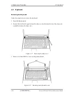
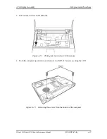
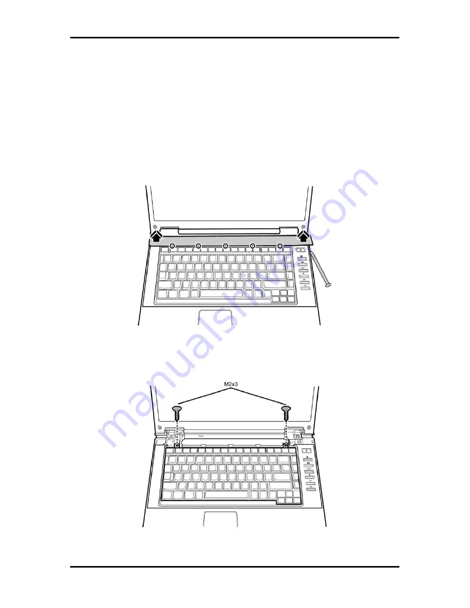
Insert a thin tool into the gap between the strip cover and keyboard to lever the strip cover 
up and then release the strip cover. 


Figure 4-17


Removing the strip cover 

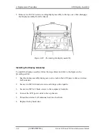
3.


Remove two black M2x3 screws securing the keyboard. 


Figure 4-18


Removing the keyboard screws 

4-20 

[CONFIDENTIAL]


Detroit 20 /Detroit 20E Series Maintenance Manual 

Содержание Satellite Pro A110

Страница 1: ...Toshiba Personal Computer Satellite A110 Satellite Pro A110 Maintenance Manual TOSHIBA CORPORATION CONFIDENTIAL ...

Страница 2: ...es at the time of this manual s production However succeeding computers and manuals are subject to change without notice Therefore Toshiba assumes no liability for damages incurred directly or indirectly from errors omissions or discrepancies between any succeeding product and this manual Trademarks IBM is a registered trademark and OS 2 and PS 2 are trademarks of IBM Corporation Microsoft MS DOS ...

Страница 3: ...ion is not observed WARNING Warning indicates the existence of a hazard that could result in bodily injury if the safety instruction is not observed CAUTION Caution indicates the existence of a hazard that could result in property damage if the safety instruction is not observed NOTE Note contains general information that relates to your safe maintenance service Improper repair of the computer may...

Страница 4: ...Troubleshooting Procedures explains how to diagnose and resolve FRU problems Chapter 3 Test and Diagnostics describes how to perform test and diagnostic operations for maintenance service Chapter 4 Replacement Procedures describes the removal and replacement of the FRUs Appendices The appendices describe the following Handling the LCD module Board layout Pin assignments Keyboard scan character cod...

Страница 5: ...ol as it appears on the keyboard is printed in boldface type Key operation Some operations require you to simultaneously use two or more keys We identify such operations by the key top symbols separated by a plus sign For example Ctrl Pause Break means you must hold down Ctrl and at the same time press Pause Break If three keys are used hold down the first two and at the same time press the third ...

Страница 6: ...vi CONFIDENTIAL Satellite A110 Satellite Pro A110 Series Maintenance Manual ...

Страница 7: ...troduction 2 1 2 2 Troubleshooting Flowchart 2 2 2 3 Power Supply Troubleshooting 2 7 2 4 Display Troubleshooting 2 12 2 5 Keyboard Troubleshooting 2 15 2 6 External USB Devices Troubleshooting 2 17 2 7 TV Out Failure Troubleshooting 2 19 2 8 Printer Port Troubleshooting 2 21 2 9 TouchPad Troubleshooting 2 23 2 10 Speaker Troubleshooting 2 27 2 11 Optical Drive Troubleshooting 2 29 2 11 Modem Trou...

Страница 8: ... 3 2 3 3 Config Check Test 3 6 3 4 DMI Check Test 3 7 3 5 PIO Loopback Test 3 8 3 6 Speaker Audio Test 3 9 3 7 Fan ON OFF Test 3 10 3 8 Main Battery Charge Test 3 11 3 9 FDD Test 3 12 3 10 CD ROM Test 3 13 3 11 Keyboard Test 3 14 3 12 Mouse Pad Test 3 16 3 13 LCD Pixels Mode Test 3 18 3 14 Lid Switch Test 3 19 3 15 HDD R W Test 3 20 3 16 LAN Test 3 22 3 17 RTC Test 3 24 ...

Страница 9: ...DD 4 10 4 5 Modem 4 12 4 6 Expansion Memory 4 13 4 7 Wireless LAN Unit 4 15 4 8 Optical Drive 4 18 4 9 Keyboard 4 20 4 10 Direct Assembly 4 22 4 11 Bluetooth 4 25 4 12 Top Cover 4 26 4 13 Touch Pad 4 28 4 14 System Board 4 29 4 15 Speakers 4 31 4 16 Thermal Module 4 32 4 17 CPU and Fan 4 33 4 18 Display Mask 4 35 4 19 LCD Module 4 36 4 20 FL Inverter Board 4 38 ...

Страница 10: ...tenance Manual Appendices Appendix A Handling the LCD Module A 1 Appendix B Board Layout B 1 Appendix C Pin Assignments C 1 Appendix D Keyboard Scan Character Codes D 1 Appendix E Key Layout E 1 Appendix F Series Screw Torque List F 1 Appendix G Reliability G 1 ...

Страница 11: ...Chapter 1 Hardware Overview 1 CONFIDENTIAL ...

Страница 12: ...1 Hardware Overview 1 ii CONFIDENTIAL Detroit 20 Detroit 20E Series Maintenance Manual ...

Страница 13: ...Chapter 1 Contents 1 1 Features 1 1 1 2 System Unit 1 6 1 3 2 5 inch Hard Disk Drive 1 8 1 4 Optical Device Drives 1 9 1 4 1 DVD ROM CD RW 1 9 1 4 2 DVD Super Multi drive supporting R Double Layer 1 10 1 5 Power Supply 1 11 1 6 Batteries 1 13 1 6 1 Main Battery 1 14 1 6 2 RTC battery 1 15 ...

Страница 14: ...oit 20 Detroit 20E Series Maintenance Manual Figures Figure 1 1 2 5 inch HDD 1 8 Tables Table 1 1 2 5 inch HDD specifications 1 8 Table 1 2 DVD ROM CD RW drive specifications 1 9 Table 1 3 DVD Super Multi Double Layer drive specifications 1 10 ...

Страница 15: ...ultiple digital media card slot ENE CB1410 for PCMCIA controller VIA6311S for IEEE1394 controller Mobile Intel 945GM Express Chipset with Realtek RTL8101E for 10M 100M LAN Mobile Intel 945GM Express Chipset with Realtek RTL8111B for 10M 100M 1Gbps LAN ATI Radeon XPRESS 200M with RTL8100CL for 10M 100M LAN Realtek ALC861 for HD CODEC Video RAM Up to 128MB integrated solution and shared with main me...

Страница 16: ... protection Power on HDD Various hot key for system control Refreshable Complete ACPI 1 0B function Power 4 cell Lithium Ion smart battery pack with 14 4V 2000mAh 6 cell Lithium Ion smart battery pack with 10 8V 4000mAh 8 cell Lithium Ion smart battery pack with 14 4V 4300mAh Approximately 12 hours or longer charging time to 100 battery capacity with system switched on Approximately 4 hours charge...

Страница 17: ...oft keys and cursor control keys TouchPad This pointing control device located in the center of the keyboard palm rest provides convenient control of the cursor without requiring desk space for a mouse The TouchPad incorporates two mouse buttons I O Ports Three USB ports V2 0 horizontal type One DDC2b compliant 15 pin VGA port 15pins RGB One type II PCMCIA slot with shutter door One RJ 11 jack for...

Страница 18: ...upport for the V 90 or V 92 standards depending on the region and provides a modem jack for connection to a telephone line Speed of data and fax transfer depends on the analog telephone line conditions LAN port The computer comes with an RJ 45 Local Area Network LAN port The LAN port provides connectivity for LAN Realtek RTL8101E or RTL8100CL On Board 10 100Mbps Realtek RTL8111B for Giga bit LAN W...

Страница 19: ...ts that comply with the USB 2 0 standard which enable data transfer speeds more than 40 times faster than USB 1 1 which this computer also supports The USB drives may be used to transfer data at Low Full and high speeds External monitor port A 15 pin CRT port supporting DDC 2B enables connection of an external monitor which is recognized automatically by Video Electronics Standards Association VES...

Страница 20: ...ntroller VIA6311S for IEEE1394 controller Mobile Intel 945GM Express Chipset with Realtek RTL8101E for 10M 100M LAN Mobile Intel 945GM Express Chipset with Realtek RTL8111B for 10M 100M 1Gbps LAN ATI Radeon XPRESS 200M with RTL8100CL for 10M 100M LAN Realtek ALC861 for HD CODEC Keyboard controller ENE KB910 is use as keyboard controller and battery management unit Memory No on board memory Mobile ...

Страница 21: ...evice Drives 1 Hardware Overview Detroit 20 Detroit 20E Series Maintenance Manual CONFIDENTIAL 1 7 Audio subsystem Realtek ALC861 HD audio Stereo speakers Sound effect by SRS software Microphone in and headphone out ...

Страница 22: ...ications are listed in Table 1 1 Figure 1 1 2 5 inch HDD Items 40GB 60GB 80GB 100GB 120GB Formatted capacity GB 37 26 55 89 74 52 93 15 111 79 Logical Blocks LBA 78 125 000 117 187 500 156 301 488 195 371 568 234 441 648 Rotational speed rpm 5400 5400 5400 5400 5400 Toshiba HDD Buffer MB 16 16 16 16 16 Hitachi HDD Buffer MB 8 8 8 8 None Fujitsu HDD Buffer MB 8 8 8 8 8 Bytes per sector 512 512 512 ...

Страница 23: ...d CD RW at 4x speed or High speed CD RW at 10x or Ultra speed CD RW at 24X speed The specifications of the DVD ROM CD RW drive are listed in Table 1 2 Item DVD ROM mode CD ROM mode Data transfer rate Mbytes s 33 3 U DMA transfer mode 2 16 6 PIO mode 4 Multiword DMA mode 2 Access time ms Average random access 180 150 Data buffer size Mbytes 2MB Formats supported DVD DVD VIDEO DVD ROM DVD R 3 9G 4 7...

Страница 24: ... DVD RW at 4x speed DVD R at 8x speed DVD RW at 4x speed DVD RAM at 5x speed DVD R DL at 2 4x speed and DVD R DL at 2x speed The specifications of the DVD Super Multi Double Layer drive are listed in Table 1 3 Item DVD ROM mode CD ROM mode Data transfer rate Mbytes s 33 3 U DMA transfer mode 2 16 6 PIO mode 4 Multiword DMA mode 2 Access time ms Average random access 180 150 Data buffer size Mbytes...

Страница 25: ... GPIO values AC adaptor connected Abnormal check The EC determines whether the condition is abnormal and if so stores an error code into the error register Input port management The EC monitors the following input signal status System power ON OFF status Direct CD power ON OFF status Beep and LED control Beep is caused by the low battery status The EC controls the following two kinds of LED DC IN ...

Страница 26: ... system will be driven by the battery for 12 more minutes LB0 The battery won t be able to drive the system after 3 minutes LB1 The battery can drive the system only during the suspend process LB2 The battery cannot drive the system New battery installation When a new battery is installed the EC communicates with the E2 PROM in the battery to read information of the newly installed battery Battery...

Страница 27: ... pack is the computer s main power source when the AC adaptor is not attached The battery specifications are listed in the table below Battery name Material Output voltage Capacity Main battery Lithium Ion 14 4V 8cell 4300mAH Main battery Lithium Ion 10 8V 6cell 4000mAH Main battery Lithium Ion 14 4V 4cell 2000mAH RTC battery Lithium Ion 3 0 V 15mAH The available of this battery is dependent on th...

Страница 28: ...rging time Normal charge power on 12 hours or longer Quick charge power off About 4 hours or longer NOTES 1 The time required for normal charge is affected by the amount of power the system is consuming Use of the fluorescent lamp and frequent disk access diverts power and lengthens the charge time 2 Using quick charge the power supply microprocessor automatically stops the charge after eight hour...

Страница 29: ... current date time and other setup information in memory while the computer is turned off The table below lists the charging time and data preservation period of the RTC battery The RTC battery is charged by the adaptor or main battery while the computer is powered on Status Time Charging Time power on About 24 hours Data preservation period full charge 1 month ...

Страница 30: ...Chapter 2 Troubleshooting Procedures 2 ...

Страница 31: ...Display Troubleshooting 2 12 2 5 Keyboard Troubleshooting 2 15 2 6 External USB Devices Troubleshooting 2 17 2 7 TV Out Failure Troubleshooting 2 19 2 8 TouchPad Troubleshooting 2 21 2 9 Speaker Troubleshooting 2 23 2 10 Optical drive troubleshooting 2 27 2 11 Modem Troubleshooting 2 30 2 12 PCMCIA Troubleshooting 2 32 2 13 IEEE 1394 Troubleshooting 2 34 2 14 Wireless LAN Troubleshooting 2 36 ...

Страница 32: ...hooting process 2 15 Figure 2 5 External USB device troubleshooting process 2 17 Figure 2 6 TV out troubleshooting process 2 19 Figure 2 7 TouchPad troubleshooting process 2 21 Figure 2 8 Speaker troubleshooting process 2 23 Figure 2 9 Optical drive troubleshooting process 2 27 Figure 2 10 Modem troubleshooting process 2 30 Figure 2 11 PCMCIA troubleshooting process 2 32 Figure 2 12 IEEE 1394 trou...

Страница 33: ......

Страница 34: ...tics Disk operations are described in Chapter 3 Detailed replacement procedures are given in Chapter 4 The following tools are necessary for implementing the troubleshooting procedures 1 Diagnostics Disk Repair and Sound Repair 2 Phillips screwdriver 2 mm 3 6mm nut driver for the helix screw nuts on the rear ports for CPU door 4 2DD or 2HD formatted work disk for floppy disk drive testing 5 Sycard...

Страница 35: ...ting procedures to execute Before performing any troubleshooting procedures verify the following z Ask the user if a password is registered and if it is ask him or her to enter the password z Verify with the customer that Toshiba Windows XP is installed on the hard disk Operating systems that were not preinstalled by Toshiba can cause the computer to malfunction z Make sure all optional equipment ...

Страница 36: ... passw ord m essage displays type the passw ord then press Enter Is Toshiba W indow s being loaded A Y es Y es Y es Y es Y es Y es Perform the Pow er Supply Troubleshooting procedures in section 2 3 Perform diagnostics program R un C M 165 EX E and select the H A R D D ISK item Perform the D isplay Troubleshooting procedures in section 2 4 Perform the Pow er Supply Troubleshooting procedures in se...

Страница 37: ...ogram Is the diagnostics test loaded Allow each test to perform automatically Is an error detected by any of the diagnostics tests System is normal End Yes Yes Yes No Perform the Keyboard Troubleshooting procedures in section 2 6 Perform the FDD Troubleshooting procedures in section 2 5 After confirming which diagnostics test has detected an error perform the appropriate procedure as outlined belo...

Страница 38: ... Supply Troubleshooting procedures in Section 2 3 2 If an error is detected by the display test perform the Display Troubleshooting procedures in Section 2 4 3 If an error is detected by the keyboard test perform the Keyboard Troubleshooting procedures in Section 2 5 4 If an error is detected by the TouchPad test perform the TouchPad Troubleshooting procedures in Section 2 8 5 If an error is detec...

Страница 39: ...Out Failure Troubleshooting procedures in Section 2 7 3 If an error is detected when using the speakers perform the Speaker Troubleshooting procedures in Section 2 9 4 If an error is detected when using the modem perform the Modem Troubleshooting procedures in Section 2 11 5 If an error is detected when using the PCMCIA unit perform the PCMCIA Troubleshooting procedures in Section 2 12 6 If an err...

Страница 40: ...C IN and Battery LEDs lit Can you turn the computer on Are the internal power connections secure END Check Power Supply Status Procedure 1 No Yes Check power supply connections Procedure 3 Run diagnostic program Procedure 4 Yes No Replace adaptor battery Procedure 2 No Perform internal connection check Procedure 5 Replace system board Yes Figure 2 2 Power Supply Troubleshooting Process ...

Страница 41: ...wer Status Check The following LEDS indicate the power supply status Battery LED DC IN LED The power supply controller displays the power supply status through the Battery and the DC IN LEDS as listed in the tables below Table 2 1 Battery LED Battery State LED colors Definition Amber solid on Battery charging with AC Green solid on Battery fully charged by AC Charging Green color off Battery abnor...

Страница 42: ...power supply status install a battery pack and connect an AC adaptor to the DC IN port on the computer and to a power supply If the DC IN LED or Battery LED is not lit go to Procedure 2 Procedure 2 Adaptor battery replacement A faulty adaptor may not supply power or may not charge the battery Perform Check 1 Check 1 Connect a new AC adaptor If the problem is not resolved go to Check 2 Check 2 Inse...

Страница 43: ...DC IN socket AC adaptor inlet and wall outlet If these cables are connected correctly go to Check 3 Check 3 Make sure that the DC IN input port socket is firmly secured to the system board of the computer If the DC IN input socket is loose go to Procedure 5 If it is not loose go to Check 4 Check 4 Use a multi meter to make sure that the AC adaptor output voltage is close to 19 V If the output is s...

Страница 44: ...the battery is functioning normally Procedure 5 Replacement check The system board may be disconnected or damaged Disassemble the computer following the steps described in Chapter 4 Replacement Procedures Check the connection between the AC adaptor and the system board After checking the connection perform Check 1 Check 1 Use a multi meter to make sure that the fuses on the system board are not bl...

Страница 45: ... isplay check P ro ced ure 1 S T A R T D o es the external d isp lay functio n o k P erfo rm d iagno stic check P ro ced ure 2 No W as a display pro b lem d etected P erfo rm co nnecto r and replacem ent check P ro ced ure 3 R eplace system bo ard E N D Y es Y es No D isplay is no t faulty C o ntinue tro ub leshoo ting refer to F igure 2 1 Figure 2 3 Display troubleshooting process ...

Страница 46: ...l monitor port then boot the computer The computer automatically detects the external display If the external display works correctly the internal LCD may be damaged Go to Procedure 3 If the external monitor appears to have the same problem as the internal monitor the system board may be damaged Go to Procedure 2 Procedure 2 Diagnostic check The Display Test program is stored on the computer s Dia...

Страница 47: ...AM module is seated properly Test display again If the problem still exits replace the DDR RAM module If the problem still exists perform Check 2 Check 2 Replace the FL inverter board with a new one and test display again If the problem still exists perform Check 3 Check 3 Replace the LCD module with a new one and test display again If the problem still exists perform Check 4 Check 4 Replace the L...

Страница 48: ...b o ard check P ro ced ure 1 S T A R T D o es the external keybo ard function ok P erfo rm d iagno stic check P ro ced ure 2 W as a keyb o ard pro b lem d etected P erfo rm co nnecto r and replacem ent check P ro ced ure 3 R eplace system bo ard E N D Y es No K eyb o ard is no t faulty C o ntinue tro ub leshoo ting refer to F igure 2 1 No Y es Figure 2 4 Keyboard troubleshooting process ...

Страница 49: ...e damaged Replace it with a new one following the instructions in Chapter 4 Procedure 2 Diagnostic check Run the Diagnostic Program which will automatically execute the Keyboard Test Refer to Chapter 3 Tests and Diagnostics for more information on how to run the program If an error is located go to Procedure 3 If an error does not occur the keyboard is functioning properly Procedure 3 Connector an...

Страница 50: ...g R ep lace system b o ard P ro ced ure 2 E N D O riginal U S B d evice is faulty P erfo rm external d evice and connection check P ro ced ure 1 S T A R T D o es the d evice functio n w hen co nnected to a d ifferent U S B p ort D o es an alternative U S B d evice functio n co rrectly No Y es No C heck U S B p o rt co nnectio n Y es Figure 2 5 External USB device troubleshooting process ...

Страница 51: ...ice into another USB socket there are three in all If the USB device still does not work go to Check 4 If the device functions correctly when connected to another USB port go to Check 3 Check 3 Make sure that the USB socket is firmly secured to the system board of the computer If the malfunction remains the system board may be damaged Go to Procedure 2 Check 4 Connect an alternative USB device to ...

Страница 52: ...2 19 2 7 TV Out Failure Troubleshooting P erfo rm T V co nnection check P ro ced ure 1 S T A R T D o es rep lacem ent T V cab le function prop erly P erfo rm T V set check P ro ced ure 2 R ep lace system b o ard E N D No R ep lace T V cab le No T V functioning o k Y es U se d ifferent T V set No Figure 2 6 TV out troubleshooting process ...

Страница 53: ...t port of the computer If the cable is connected correctly go to Check 2 Check 2 Make sure the TV out port is firmly secured to the system board of the computer If the malfunction remains go to Check 3 Check 3 The TV cable may be damaged Replace with a good cable If the malfunction remains go to Procedure 2 Procedure 2 TV set check The TV set may be faulty Perform Check 1 Check 1 Try using the set...

Страница 54: ... Satellite A110 Satellite Pro A110 Series Maintenance Manual CONFIDENTIAL 2 21 2 8 TouchPad Troubleshooting START END TouchPad connection check Procedure 1 TouchPad replacement check Procedure 2 Replace system board Figure 2 7 TouchPad troubleshooting process ...

Страница 55: ... via the TouchPad FPC to the system board Make sure the TouchPad FPC cable is firmly connected to the TouchPad and system board Refer to Chapter 4 Replacement Procedures for instructions on how to disassemble the computer and then perform the following checks If any of the connections are loose reconnect firmly If any of the connections is damaged or there is still an error go to Procedure 2 Proce...

Страница 56: ... START Do all sources have same problem END Perform earphone test Procedure 2 Do earphones function correctly Perform connection check Procedure 3 Perform replacement check Procedure 4 Perform audio source test Procedure 1 No Yes Yes Replace system board Speakers are not faulty Continue troubleshooting see Figure 2 1 No Figure 2 8 Speaker troubleshooting process ...

Страница 57: ...l sources have sound problem the problem is in the source devices If all have the same problem continue with Procedure 2 Procedure 2 Earphone test Connect a set if earphones or external speakers If these function correctly go to Procedure 3 If they do not function correctly the system board may be defective or damaged Replace it with a new one Procedure 3 Connection check Disassemble the computer ...

Страница 58: ...erform software check Procedure 3 Perform diagnostic test Procedure 4 Perform connection and replacement check Procedure 5 Perform audio CD check Procedure 1 Perform drive cleaning check Procedure 2 No Yes Replace system board Figure 2 9 Optical drive troubleshooting process Satellite A110 Series Maintenance Manual CONFIDENTIAL 2 27 ...

Страница 59: ...edure 1 Audio CD check First insert an audio CD into the CD DVD drive If it works the problem is not with the drive Go to Procedure 3 If the audio CD does not work go to Procedure 2 If the CD DVD LED on the front panel does not light when the disc is played and the drive gives no response go straight to Procedure 3 Procedure 2 Drive cleaning check Insert a CD DVD drive cleaning disk into the drive...

Страница 60: ...ribed in Chapter 4 Replacement Procedures and perform the following checks Check 1 Make sure the drive is firmly connected to the system board If the connection is good and there is still an error go to Check 2 Check 2 The drive or drive cable may be defective or damaged Replace each with a new one following the steps in Chapter 4 Replacement Procedures If the drive is still not functioning proper...

Страница 61: ... Computer unable to detect telephone signal END Perform telephone line connection check Procedure 1 Check replace telephone line and connections defect disappear Replace system board Yes No Figure 2 10 Modem troubleshooting process 2 30 CONFIDENTIAL Satellite M70 Series Maintenance Manual ...

Страница 62: ...pt to connect the computer to a network through using the modem If the modem does not function at all go to Procedure 3 If the attempt fails because the computer detects no telephone signal the fault may be in the telephone cable the wall socket or the modem port Perform Check 1 Check 1 Make sure telephone cable is firmly plugged into both the telephone wall socket and the modem port of the comput...

Страница 63: ...g START Do errors occur during SYCARD test Perform PCMCIA socket replacement check Procedure 2 Replace system board END PCMCIA unit is not faulty Perform SYCARD test Procedure 1 No Yes Figure 2 11 PCMCIA troubleshooting process 2 32 CONFIDENTIAL Satellite M70 Series Maintenance Manual ...

Страница 64: ...he SYCARD test card contains a PCMCIA test program Ensure the card in fully inserted into the socket before running the program If an error occurs during the SYCARD test perform Procedure 2 If no error occurs it is likely that the original PC card was faulty Procedure 2 PCMCIA socket replacement check The PCMCIA socket may be damaged or defective for instance the socket pins can be bent Disassembl...

Страница 65: ...on ok Perform diagnostic check Procedure 2 Was an IEEE 1394 problem detected Perform connection and replacement check Procedure 3 Replace system board END Yes Yes IEEE 1394 port and transmission are not faulty Continue troubleshooting refer to Figure 2 1 No No Figure 2 12 IEEE 1394 troubleshooting process 2 34 CONFIDENTIAL Satellite M70 Series Maintenance Manual ...

Страница 66: ...red there may be a faulty connection Go to Procedure 3 Procedure 2 Diagnostic check Run the Diagnostic Program which will automatically execute the IEEE 1394 port test for transmission Refer to Chapter 3 Tests and Diagnostics for more information on how to run the program If an error is located go to Procedure 3 If an error does not occur the 1394 port is functioning properly Procedure 3 Connectio...

Страница 67: ...gnostic test Procedure 1 Was a wireless LAN problem delected Perform connector and replacement check Procedure 2 Replace wireless LAN antenna unit Replace system board END Yes Wireless LAN system is not faulty Continue troubleshooting refer to Figure 2 1 No 2 36 CONFIDENTIAL Satellite M70 Series Maintenance Manual ...

Страница 68: ...2 14 Wireless LAN Troubleshooting 2 Troubleshooting Procedures Satellite A110 Series Maintenance Manual CONFIDENTIAL 2 37 Figure 2 13 Wireless LAN troubleshooting process ...

Страница 69: ...eless LAN unit or system board may be disconnected or damaged Disassemble the computer following the steps described in Chapter 4 Replacement Procedures and perform the following checks Check 1 Make sure that the wireless LAN antenna is firmly connected to the wireless LAN unit refer to Chapter 4 for instructions and that the wireless LAN unit is securely slotted into the system board If the probl...

Страница 70: ...3 1The Diagnostic Test 3 Tests and Diagnostics 3 1 Satellite A110 Series Maintenance Manual Chapter 3 Tests and Diagnostics 3 ...

Страница 71: ...3 6 Fan ON OFF Test 3 11 3 7 Main Battery Charge Test 3 11 3 8 FDD Test 3 12 3 9 ODD Test 3 13 3 10 Keyboard Test 3 14 3 11 Mouse Pad Test 3 17 3 12 LCD Pixels Mode Test 3 19 3 13 Magnetic switch Test 3 20 3 14 HDD R W Test 3 21 3 15 LAN Test 3 23 3 16 RTC Test 3 26 3 17 Read 1394 GUID 3 27 3 18 Button Test 3 28 3 2 Satellite A110 Series Maintenance Manual ...

Страница 72: ...onnections 2 Exit this program when you are at Main Menu The TEST DIAGNOSTIC PROGRAM contains the following functional tests CONFIG CHECK TEST DMI CHECK TEST SPEAKER AUDIO TEST FAN ON OFF TEST MAIN BATTERY CHARGE TEST FDD TEST ODD TEST KEYBOARD TEST MOUSE PAD TEST LCD PIXELS MODE TEST MAGNETIC SWITCH TEST HDD R W TEST LAN TEST RTC TEST IEEE1394 CODE TEST Button Test You will need the following equ...

Страница 73: ... make sure the CD is installed in the ODD drive The T D Program can run by single test item when you press corresponsive English letter of test item or run two or more test items what you like if you choose them by Arrow cursors and Space Bar the wonderful thing is you can setup test loop by Enter button And it also asks you if you like to copy test log file to diskette as reference at the end of ...

Страница 74: ...g the Diagnostic Test 3 Tests and Diagnostics The below display will show up at the beginning of T D program If the test result passes the following display will show up 3 5 Satellite A110 Series Maintenance Manual ...

Страница 75: ...r is detected and a test fails the following message displays Then press any key for next actions the below display presented if copying test log file onto diskette is necessary This action will be executed when Y key pressed 3 6 Satellite A110 Series Maintenance Manual ...

Страница 76: ...stics It will skip this process if N key pressed And then it will check if it s necessary to leave this program Program will quit when Y key pressed and it will go back main menu for next test if N key pressed 3 7 Satellite A110 Series Maintenance Manual ...

Страница 77: ...cludes CPU type Single Dual Yunah Cache CPU speed CPU FSB DDRAM SIZE ODD TYPE DVD SuperMulti COMBO Panel ID HDD type capacity Vendor ID Model Firmware VRAM size VGA CHIP TYPE Battery cell 6cell 9cell 12cell Wireless type 1394 SKU ID Part Number The screen should display as below 3 8 Satellite A110 Series Maintenance Manual ...

Страница 78: ...on Name Version UUID OEM String It needs to input unit Part Number by manual then show this unit DMI information and makes comparison with Part Number data NOTE To execute this test you must input unit Part Number as Uppercase Character The screen should display as below indicating whether the test is passed or failed after comparison 3 9 Satellite A110 Series Maintenance Manual ...

Страница 79: ...onfirm the speaker functions And check both speakers if they are OK within 3 times Beep sound generated NOTE Remember to tune up the volume as Maximum before this test starts The screen should display as below indicating whether the test is passed or failed after the question 3 10 Satellite A110 Series Maintenance Manual ...

Страница 80: ...r to approach fan outlet that is near right side of unit whether fan is ON The computer will stop the fan working after any key pressed Listen to check if the fan is OFF it means no rotating sound The screen should display as below indicating whether the test is passed or failed after the question 3 7 Main Battery Charge Test NOTE The AC adaptor 65W 19V should be connected to successfully run this...

Страница 81: ...s 100 The screen should display as below indicating whether the test is passed or failed when finished 3 8 FDD Test NOTE Before running the FDD test prepare a formatted work diskette 1 44 MB Remove the diagnostics diskette and insert the work diskette into the FDD The contents of the floppy diskette maybe erased The Floppy Disk Test includes three subtests of the 3 12 Satellite A110 Series Mainten...

Страница 82: ...te should be Disable The subtests run automatically NOTE Press Esc key can skip the current subtest The screen should display as below indicating whether the subtests pass or fail when finished 3 9 ODD Test The ODD test allows a user to aurally confirm the ODD functions NOTE A CD disc including data file must be inserted into the ODD drive before this test starts The ODD test includes two subtests...

Страница 83: ...ess Esc key can skip the current subtest The screen should display as below indicating whether the subtests pass or fail when finished 3 10 Keyboard Test The keyboard test checks the all keys function NOTE The Num Lock and the Overlay mode must be off to execute the keyboard test Before keyboard test starts the keyboard matrix code should be chosen as below display 1 K UK for Europe 2 S US for Ame...

Страница 84: ...creen changes to black as shown below It will indicate whether the subtest is passed or failed after the question NOTE The Fn key cannot be tested in the keyboard test To determine whether the Fn key is working correctly press Fn F6 or Fn F7 keys to check if LCD display brightness change gradually Fn F6 Fn Up Fn F7 Fn Down 3 15 Satellite A110 Series Maintenance Manual ...

Страница 85: ...3 Tests and Diagnostics 3 10 Keyboard Test 3 16 Satellite A110 Series Maintenance Manual ...

Страница 86: ...ion Off Low Medium High 3 Button Assignments Left Right Right button either Unassigned or Drag Lock 4 Swap Buttons Left Right NOTE The Touch Pad test cannot be used to test an external USB mouse The Touch Pad button subtest allows users to test their Touch Pad buttons If the buttons are clicked the cursors should appear in the corresponding box of the button figure that is displayed on the screen ...

Страница 87: ...ion use Tab key or use T Pad cursor to click the OK column will end this test It will indicate whether the subtests pass or fail after three questions NOTE The above figure has three compartments although the Touch Pad installed may only have two buttons In this case the central compartment in the figure does not correspond to any button ...

Страница 88: ...of the test 1 Text Mode including 40 25 16 colors and 80 25 2 16colors 2 VGA Mode including 320 200 4 16 256 colors 640 200 2 16 colors 640 350 2 16 colors 640 480 2 16 256 colors 800 600 256 colors and 1024 768 256 colors The screen should display as below indicating whether the test is passed or failed after the question 3 19 Satellite A110 Series Maintenance Manual ...

Страница 89: ...closed the lid should enable to turn off the display NOTE Remember to tune up the volume as Maximum before this test starts Follow below steps to run this test 1 Close the LCD cover 2 Heard 3 Beep sound happened during LCD closed 3 Open the LCD Then it will indicate whether the test is passed or failed 3 20 Satellite A110 Series Maintenance Manual ...

Страница 90: ...tion For data security concern it is necessary to input password hard disk before HDD test starts After the choice HDD test Screen would display as below If input password is Right the screen would display as below Press any key to test HDD function the screen would display as below 3 21 Satellite A110 Series Maintenance Manual ...

Страница 91: ...rong the screen would display as below The screen should display as previous picture indicating whether the subtest is passed or failed when finished NOTE The AC adaptor should be connected to successfully run this test 3 22 Satellite A110 Series Maintenance Manual ...

Страница 92: ...nd LAN information will show on the test screen IO Base Port A000H IRQ BH it s IRQ 10 Node it is MAC Address Line Frame 1514 Bytes Line Speed 100Mbps or 10 Mbps Bus ID it s 4 The LAN test includes two subtests of the 1 Speed100 Including Ethernet_802 2 Ethernet II Ethernet SNAP and Ethernet_802 3 All test items are in LSB mode 2 Speed10 Including Ethernet_802 2 in LSB mode The subtests run automat...

Страница 93: ...3 Tests and Diagnostics 3 15 LAN Test The screen should display as below indicating whether the subtests pass or fail when finished 3 24 Satellite A110 Series Maintenance Manual ...

Страница 94: ...3 15 LAN Test 3 Tests and Diagnostics If an error is detected and a test fails the following message displays 3 25 Satellite A110 Series Maintenance Manual ...

Страница 95: ...e computer s RTC Real Time Clock and calendar functions by comparing the DOS and CMOS values The test runs automatically The screen should display as below indicating whether the test is passed or failed when finished 3 26 Satellite A110 Series Maintenance Manual ...

Страница 96: ...ead 1394 GUID This test will check if the computer s EEPROM 1394GUID code is correct NOTE Must open the RAM Door to see RAM connector GUID bar code before test item begins The figure below will be displayed 3 27 Satellite A110 Series Maintenance Manual ...

Страница 97: ... the button test should be chosen as below display 1 1 1 button 2 2 6 button When you execute this test the button test choice show on the display When any key is pressed The corresponding key on the screen changes to black as shown below 3 28 Satellite A110 Series Maintenance Manual ...

Страница 98: ...When you choice 2 The control button test allows the user to manually test each of the five CD control buttons Key WWW need to press first One will hear one bi sound when press WWW or Audio Sound and continuously bi sound for another key test The figure below will be displayed 3 29 Satellite A110 Series Maintenance Manual ...

Страница 99: ...iagnostics Press each of the buttons on the front panel in turn A yellow bar will appear on the relevant section of the figure if the button passes the test Press Ctrl C to quit the test 3 30 Satellite A110 Series Maintenance Manual ...

Страница 100: ...4 Chapter 4 Replacement Procedures CONFIDENTIAL ...

Страница 101: ...4 Replacement Procedures 4 ii CONFIDENTIAL Detroit 20 Detroit 20E Series Maintenance Manual ...

Страница 102: ... HDD 4 10 4 5 Modem 4 12 4 6 Expansion Memory 4 13 4 7 Wireless LAN Unit 4 15 4 8 Optical Drive 4 18 4 9 Keyboard 4 20 4 10 Display Assembly 4 22 4 11 Bluetooth 4 25 4 12 Top Cover 4 26 4 13 TouchPad 4 28 4 14 System Board 4 29 4 15 Speakers 4 31 4 16 Thermal Module 4 32 4 17 CPU and Fan 4 33 4 18 Display Mask 4 35 4 19 LCD Module 4 36 4 20 FL Inverter Board 4 38 ...

Страница 103: ...4 14 Removing the optical drive screw 4 18 Figure 4 15 Removing the optical drive 4 18 Figure 4 16 Removing the optical drive bracket 4 19 Figure 4 17 Removing the strip cover 4 20 Figure 4 18 Removing the keyboard screws 4 20 Figure 4 19 Disconnecting the keyboard cable 4 21 Figure 4 20 Disconnecting the LCD cable 4 22 Figure 4 21 Removing the keyboard door 4 22 Figure 4 22 Pulling out the wirele...

Страница 104: ...4 34 Removing the thermal module 4 32 Figure 4 35 Removing the CPU 4 33 Figure 4 36 Disconnecting the fan wire 4 33 Figure 4 37 Removing the fan screws 4 34 Figure 4 38 Removing the display mask screws 4 35 Figure 4 39 Removing the LCD module screws 4 36 Figure 4 40 Removing the connectors 4 36 Figure 4 41 Removing the bracket screws 4 37 Figure 4 42 Removing the FL inverter board 4 38 ...

Страница 105: ...4 Replacement Procedures 4 vi CONFIDENTIAL Detroit 20 Detroit 20E Series Maintenance Manual ...

Страница 106: ...to be removed in order to remove others Always start by removing the battery pack next optional items such as the optional PC Card then follow the chart downward removing only those FRUs necessary to reach the one you think is causing the computer to operate improperly Refer to the example on the following page Battery pack Keyboard Wireless LAN HDD and or Modem ODD and Expansion Memory Module Blu...

Страница 107: ...rlapped by the top cover that must be removed before it can be reached The removable keyboard and display assembly in turn overlap the top cover Always starts the disassembly process by removing the battery pack Battery pack Keyboard Wireless LAN HDD and or Modem ODD and Expansion Memory Module Bluetooth Display Assembly Top Cover Display Mask System Board LCD Module Fan Thermal Module CPU Speaker...

Страница 108: ...om the power source 2 Remove any metal jewelry or accessories such as necklaces bracelets or rings Batteries in the computer retain an electrical charge so there is danger of electrical shock even when the computer is disconnected from an AC power source 3 Never work with wet or damp hands 4 The computer contains sharp edges and corners be careful not to injure yourself 5 Make sure that all replac...

Страница 109: ...ary troubleshooting and diagnostics tests described in chapters 2 and 3 of this manual 5 Do not perform any operations that are not necessary and use only the described procedures for disassembling and installing FRUs in the computer 6 After removing parts from the computer place them in a safe place away from the computer so they will not be damaged and will not interfere with your work 7 You wil...

Страница 110: ... These connectors can be connected and disconnected by simply pulling them apart or pushing them together Assembly Procedures After you have disassembled the computer and fixed or repaired the problem that was causing the computer to operate abnormally you will need to reassemble the computer Install all the removed FRUs following the steps described in the corresponding sections in this chapter W...

Страница 111: ...the success rate of your repairs and lower the cost for damaged or destroyed parts The following equipment is necessary to disassemble and reassemble the computer One M2 Phillips screwdriver to remove and replace screws One T8 security screwdriver Tweezers to lift out screws that you cannot grasp with your fingers ESD mats for the floor and the table you are working on ESD wrist strap or heel grou...

Страница 112: ...sons do not throw away a spent battery pack Please return spent battery packs to Toshiba Installing the Battery Pack To install the battery pack in the battery bay follow the steps below and refer to the figure in the preceding section WARNING The battery is a lithium ion battery and can explode if not properly replaced used handled or disposed of Use only batteries recommended by Toshiba as repla...

Страница 113: ...y Remove Hardware icon on the Task Bar 2 Click the PC Card you want to remove 3 Press the eject button of the PC Card to extend it 4 Press the extended eject button to pop the card out slightly 5 Grasp the PC Card and remove it Figure 4 2 Pressing the eject button 4 8 CONFIDENTIAL Detroit 20 Detroit 20E Series Maintenance Manual ...

Страница 114: ...es Installing the PC Card To install the PC Card follow the steps below 1 Insert the PC Card 2 Press gently to ensure a firm connection Figure 4 3 Installing the PC card Detroit 20 Detroit 20E Series Maintenance Manual CONFIDENTIAL 4 9 ...

Страница 115: ...Removing the HDD Module Follow the steps below to remove HDD module 1 Turn the computer upside down 2 Remove three black M2 5x4 safety screws to release the HDD door 3 Remove three black M2 5x3 screws from the HDD unit 4 Pull on the tab to remove the HDD unit Figure 4 5 Removing the HDD unit 4 10 CONFIDENTIAL Detroit 20 Detroit 20E Series Maintenance Manual ...

Страница 116: ...g the HDD To install the HDD follow the steps below and refer to the figures in the preceding section 1 Seat the HDD in the EMI Shielding and secure it with four black M3x3 screws 2 Insert the HDD unit into the HDD slot 3 Secure the HDD with three black M2 5x3 screws 4 Secure the HDD door with three black M2 5x4 safety screws Detroit 20 Detroit 20E Series Maintenance Manual CONFIDENTIAL 4 11 ...

Страница 117: ...e 4 7 Removing the modem screws 2 Disconnect the RJ 11 wire then lift out the modem NOTE The Detroit 20E does not have a modem so this does not apply Installing the Modem To install a modem follow the steps below and refer to the figures in the preceding section 1 Connect the modem cable to the modem module 2 Fit the modem onto its connector and secure it with one black M2 5x3 screw 4 12 CONFIDENT...

Страница 118: ...Push the latches securing the memory module to the outside to release it A A spring will force one end of the module up B 3 Grasp the module and pull it out C 4 Seat the cover and secure its screw Figure 4 8 Removing the expansion memory CAUTION Do not touch the connectors on the expansion memory or on the computer Debris on the connectors may cause memory access problems Detroit 20 Detroit 20E Se...

Страница 119: ...le follow the steps below and refer to the figures in the preceding section 1 Fit the module s connectors into the computer s connectors at about a 45 degree angle and press the module carefully to ensure a firm connection A 2 Push the module down so it lies flat B Latches on either side will click into place to secure the module Figure 4 9 Installing the expansion memory 4 14 CONFIDENTIAL Detroit...

Страница 120: ...less LAN unit 1 Remove the black M2x4 screw securing the wireless LAN door and then remove it Figure 4 10 Removing the wireless LAN door 2 Disconnect the antenna wires from the wireless LAN module Figure 4 11 Removing the wireless LAN antenna wires Detroit 20 Detroit 20E Series Maintenance Manual CONFIDENTIAL 4 15 ...

Страница 121: ... Figure 4 12 Removing the wireless LAN unit screws 4 Grasp the wireless LAN unit and pull it out Figure 4 13 Removing the wireless LAN card CAUTION Do not touch the connectors on the wireless LAN unit or on the computer Debris on the connectors may cause malfunction 4 16 CONFIDENTIAL Detroit 20 Detroit 20E Series Maintenance Manual ...
Страница 122: ...ove it CAUTION Do not touch the connectors on the wireless LAN unit or on the computer Debris on the connectors may cause malfunction 2 Fit the wireless LAN unit connector into the computer s connectors and secure it with two black M2 5x3 screws 3 Place the wireless LAN unit in the wireless LAN holder and gently press down Secure the wireless LAN unit with two M2 5x4 screws 4 Attach the white ante...

Страница 123: ...e Optical Drive To disassemble the optical drive follow the steps below 1 Remove the black M2 5x3 screw securing the optical drive Figure 4 14 Removing the optical drive screw 2 Use your finger to slide out the optical drive in direction of the arrow Figure 4 15 Removing the optical drive 4 18 CONFIDENTIAL Detroit 20 Detroit 20E Series Maintenance Manual ...

Страница 124: ...semble an optical drive follow the steps below and refer to the figure in the preceding section 1 Position the optical drive bracket plate to the rear panel of optical drive 2 Secure the optical drive bracket plate with two black M2x3 screws 3 Install the optical drive into the bay and use the black M2 5x3 screw to secure the optical drive Detroit 20 Detroit 20E Series Maintenance Manual CONFIDENT...

Страница 125: ...y panel 2 Insert a thin tool into the gap between the strip cover and keyboard to lever the strip cover up and then release the strip cover Figure 4 17 Removing the strip cover 3 Remove two black M2x3 screws securing the keyboard Figure 4 18 Removing the keyboard screws 4 20 CONFIDENTIAL Detroit 20 Detroit 20E Series Maintenance Manual ...

Страница 126: ... install the keyboard follow the steps below and refer to the figures in the preceding section 1 Connect the keyboard FPC cable to the system board 2 Set the keyboard in place and secure it with two black M2x3 screws 3 Set the strip cover in place and press down to secure the strip cover latches engage Detroit 20 Detroit 20E Series Maintenance Manual CONFIDENTIAL 4 21 ...

Страница 127: ...remove the keyboard and wireless LAN then follow the steps below 1 Disconnect the LCD power cable from the top chassis Figure 4 20 Disconnecting the LCD cable 2 Remove the keyboard door on the left hand side of the computer chassis Figure 4 21 Removing the keyboard door 4 22 CONFIDENTIAL Detroit 20 Detroit 20E Series Maintenance Manual ...
Страница 128: ...LAN antennas Figure 4 22 Pulling out the wireless LAN antennas 4 Turn the computer upside down and remove two M2 5x12 screws securing the LCD Figure 4 23 Removing the screws from the bottom of the computer Detroit 20 Detroit 20E Series Maintenance Manual CONFIDENTIAL 4 23 ...

Страница 129: ...e steps below and refer to the figures in the preceding section 1 Seat the display assembly taking care not to crush to the LCD power cable or wireless LAN antenna 2 Secure two M2 5x6 black screws to each hinge on the topside 3 Secure two M2 5x12 black screws to the computer s backside 4 Connect the LCD power cable to the top chassis 5 Thread the wireless LAN antennas back into their hole 6 Replac...

Страница 130: ... 3 Remove two black M2x3 screws securing the Bluetooth module to the chassis Figure 4 25 Removing the Bluetooth module Installing the Bluetooth module To install the Bluetooth module follow the steps below and refer to the figures in the preceding section 1 Seat the Bluetooth module on the chassis then secure it with two black M2x3 screws 2 Connect the Bluetooth FFC to the module 3 Connect the ant...

Страница 131: ...ess LAN as described in the preceding sections then follow the steps below 1 Remove one silver M2 5x13 screw two M2 5x6 screws and one M2 5x3 screw securing top cover Figure 4 26 Removing the top cover front panel screws 2 Detach the Power Switch FFC cable and TouchPad FFC cable on the top chassis Figure 4 27 Removing the cables 4 26 CONFIDENTIAL Detroit 20 Detroit 20E Series Maintenance Manual ...

Страница 132: ...er Installing the Top Cover To install the top cover follow the steps below and refer to the figures in the preceding section 1 Seat the top cover and secure the upper FFC cable and Touchpad FFC cable to the computer s top chassis 2 Secure the top cover with one silver M2 5x13 screw two M2 5x6 screws and one M2 5x3 screw 3 Turn the computer upside down and secure eleven M2 5x12 three M2 5x8 and on...

Страница 133: ...hielding Slide and lift out the TouchPad EMI Shielding Figure 4 29 Removing the TouchPad Installing the TouchPad To install the TouchPad follow the steps below and refer to the figures in the preceding section 1 With the top cover upside down place the TouchPad the Track Pad Bracket and control button board in position 2 Secure the TouchPad Bracket with three silver M2 5x3 screws 3 Secure the cont...

Страница 134: ...ecuring the Express Bracket and two M2 5x3 screws securing the Express PC Board Lift out the Express Bracket and Express PC Board 2 Remove four M2 5x3 screws from the system board Figure 4 30 Removing the system board screws 3 Remove two hexagonal screws from the back of the system board Figure 4 31 Removing the hexagonal screws Detroit 20 Detroit 20E Series Maintenance Manual CONFIDENTIAL 4 29 ...

Страница 135: ...l the system board follow the steps below and refer to the figures in the preceding section 1 Seat the system board in the chassis 2 Secure two hexagonal screws to the back of the system board 3 Secure four M2 5x3 screws to the system board 4 Seat the Express PC Board and Express Bracket and secure their screws 4 30 CONFIDENTIAL Detroit 20 Detroit 20E Series Maintenance Manual ...
Страница 136: ...ve two M2 5x3 screws from the left speaker Figure 4 33 Removing the speaker screws 3 Lift out the speakers Installing the Speakers To install the speakers follow the steps below and refer to the figure in the preceding section 1 Seat each speaker in the chassis 2 Secure the left speaker with two M2 5x3 screws 3 Secure the right speaker with two M2 5x3 screws Detroit 20 Detroit 20E Series Maintenan...

Страница 137: ... thermal module NOTE After you remove the thermal module you should use the CPU grease tool to remove the grease on the CPU and thermal module Be sure to replace the thermal grease on the CPU when you reinstall it Installing the Thermal Module To install the thermal module follow the steps below and refer to the figures in the preceding section 1 Restore the thermal grease to the top of the CPU 2 ...

Страница 138: ...llow the steps below 1 After removing the thermal module remove the CPU by turning the marked cam to disengage the mechanism that locks the CPU in place and then lifting it out Figure 4 35 Removing the CPU 2 Disconnect the fan wire from the system board Figure 4 36 Disconnecting the fan wire Detroit 20 Detroit 20E Series Maintenance Manual CONFIDENTIAL 4 33 ...

Страница 139: ...l the CPU and Fan follow the steps below and refer to the figures in the preceding section 1 Secure the fan with three M2 5x6 fan screws on the bottom of the system board 2 Connect the fan wire to the system board 3 Reinstall the CPU ensuring that you restore the thermal grease on its surface and then turn the cam back to the locked position 4 34 CONFIDENTIAL Detroit 20 Detroit 20E Series Maintena...

Страница 140: ...mask screws 2 Carefully insert your fingers or use a thin tool into the gap between the display mask and the LCD cover and gently pry open each side of the display mask to remove it Installing the Display Mask To install the display mask follow the steps below and refer to the figures in the preceding section 1 Seat the display mask and secure the snaps on each side 2 Secure the display mask with ...

Страница 141: ...w the steps below 1 Remove one M2 5x3 black screw securing the LCD cable 2 Remove two M2 5x6 black screws securing the LCD module bracket to LCD cover Figure 4 39 Removing the LCD module screws 3 Disconnect the two connectors on either side of the FL inverter board Figure 4 40 Removing the connectors 4 36 CONFIDENTIAL Detroit 20 Detroit 20E Series Maintenance Manual ...

Страница 142: ...le unit Installing the LCD Module To install the LCD module follow the steps below and refer to the figures in the preceding section 1 Set the LCD module in the display assembly with the LCD module bracket and eight black M2x3 screws Secure the LCD module with two black M2 5x6 screws 2 Connect the two connectors on either side of the FL inverter board 3 Secure one M2 5x3 black screw holding the LC...

Страница 143: ...e black M2x3 screw securing the FL invert board to the LCD cover 2 Lift out the FL invert board Figure 4 42 Removing the FL inverter board Installing the FL Inverter Board To install the FL inverter board follow the steps below and refer to the figure in the preceding section 1 Seat the FL invert board on the LCD cover then secure it with one black M2x3 screw 2 Reassemble the computer 4 38 CONFIDE...

Отзывы: