Satellite L450D / ProL450D Series Maintenance Manual
[CONFIDENTIAL]
xi
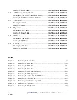
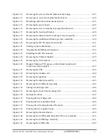
Figure 4.12
Removing the screws from the bottom of the laptop ......................................... 4-23
Figure 4.13
Removing six screws from under the keyboard................................................. 4-24
Figure 4.14
Detaching cables from under the keyboard ....................................................... 4-25
Figure 4.15
Removing the power board................................................................................ 4-26
Figure 4.16
Removing the screws from the touch pad button board .................................... 4-27
Figure 4.17
Removing the touch pad bracket ....................................................................... 4-28
Figure 4.18
Removing the thermal fan from the logic lower assembly ................................ 4-29
Figure 4.19
Removing the motherboard from logic lower assembly.................................... 4-30
Figure 4.20
Removing the DC IN connector and cable ........................................................ 4-31
Figure 4.21
Picking up the motherboard ............................................................................... 4-31
Figure 4.22
Aligning the motherboard connectors................................................................ 4-32
Figure 4.23
Installing the DC IN connector .......................................................................... 4-33
Figure 4.24
Removing the Thermal Module ......................................................................... 4-35
Figure 4.25
Removing the VGA Board................................................................................. 4-36
Figure 4.26
Reapply Shinetsu 7726 grease on the thermal module and
remove any release papers ................................................................................. 4-37
Figure 4.27
Removing the CPU ............................................................................................ 4-38
Figure 4.28
Removing the modem card ................................................................................ 4-40
Figure 4.29
Removing the speakers ...................................................................................... 4-41
Figure 4.30
Removing the display assembly......................................................................... 4-43
Figure 4.31
Removing the LCD Bezel Assembly ................................................................. 4-45
Figure 4.32
Taking out the hinge wall .................................................................................. 4-46
Figure 4.33
Removing the bezel from the hinge wall ........................................................... 4-46
Figure 4.34
Reroute the cables .............................................................................................. 4-47
Figure 4.35
Pressing the bezel hinge wall............................................................................. 4-48
Figure 4.36
Pressing the bezel downside hook ..................................................................... 4-48
Figure 4.37
Pressing the left and right side of the bezel ....................................................... 4-49
Figure 4.38
Pressing the bezel upside hooks......................................................................... 4-49
Figure 4.39
Removing the Inverter Board ............................................................................ 4-50
Figure 4.40
Removing the LCD Module from the LCD cover assembly ............................. 4-51
Figure 4.41
Removing the LCD Hinge Assembly ................................................................ 4-51
Figure 4.42
Removing the LVDS cable ................................................................................ 4-52
Содержание Satellite L450 series
Страница 1: ...Toshiba Personal Computer Satellite Maintenance Manual TOSHIBA CORPORATION CONFIDENTIAL ...
Страница 14: ...Chapter 1 Hardware Overview ...
Страница 17: ......
Страница 33: ...Chapter 2 Troubleshooting Procedures 2 ...
Страница 34: ......
Страница 82: ...3 Tests and Diagnostics 1 Chapter 3 Tests and Diagnostics ...
Страница 84: ...3 Tests and Diagnostics 3 3 19 1st HDD Test 33 3 19 2nd HDD Test 35 3 21 Read DMI 39 3 22 Write DMI 39 ...
Страница 98: ...3 Tests and Diagnostics 17 Memory Write Test Memory Read Write Test ...
Страница 104: ...3 Tests and Diagnostics 23 2 If the Magnetic switch test pass it will show below display ...
Страница 107: ...3 Tests and Diagnostics 26 If an error is detected and a test fails the following message displays ...
Страница 119: ...3 Tests and Diagnostics 38 If the picture shows as below it means he HDD function is NG ...
Страница 123: ...Chapter 4 Replacement Procedures ...
Страница 187: ...B 4 CONFIDENTIAL Low Cost Los Angeles 10AL Maintenance Manual PJP1 AC Adaptor conn PJP2 Battery conn ...
Страница 209: ...3 Thai TI Keyboard Figure TI keyboard 4 Korean KO Keyboard Figure KO keyboard ...
Страница 210: ...5 United Kingdom UK Keyboard Figure UK keyboard 6 US International UI Keyboard Figure UI keyboard ...
Страница 211: ...7 Hebrew HB Keyboard Figure HB keyboard 8 Danish DM Keyboard Figure DM keyboard ...
Страница 212: ...9 Swiss SW Keyboard Figure SW keyboard 10 Arabic ARE Keyboard Figure ARE keyboard ...
Страница 213: ...11 Czech CZ Keyboard Figure CZ keyboard 12 Russian RU Keyboard Figure RU keyboard ...
Страница 214: ...13 Portuguese PO Keyboard Figure PO keyboard 14 Slovakian SL Keyboard Figure SL keyboard ...
Страница 215: ...15 Italian IT Keyboard Figure IT keyboard 16 French FR Keyboard Figure FR keyboard ...
Страница 216: ...17 German GR Keyboard Figure GR keyboard 18 Greek GK Keyboard Figure GK keyboard ...
Страница 217: ...19 Canada French CF Keyboard Figure CF keyboard 20 Hungarian HG Keyboard Figure HG keyboard ...
Страница 218: ...21 Spanish SP Keyboard Figure SP keyboard 22 Turkish TR Keyboard Figure TR keyboard ...
Страница 219: ...3 Turkish F TF F Keyboard Figure TF F keyboard 24 Swedish SD Keyboard Figure SD keyboard ...
Страница 220: ...25 Belgian BE Keyboard Figure BE keyboard 26 Yugoslavian YU Keyboard Figure YU keyboard ...
Страница 221: ...27 Norwegian NW Keyboard Figure NW keyboard 28 Scandinavian ND Keyboard Figure ND keyboard ...
Страница 222: ...29 Canadian Multinational AC Keyboard Figure AC keyboard 30 Canadian Bilingual CB Keyboard Figure CB keyboard ...
Страница 223: ...31 Japanese JP Keyboard Figure JP keyboard 32 Romania RO Keyboard Figure RO keyboard ...
Страница 224: ...32 Bulgaria BU Keyboard Figure BU keyboard ...


