background image

User's Manual

T

ROUBLESHOOTING

9-6

Battery

If you suspect a problem with the battery, check the 

DC IN

 indicator as well as the

Battery

 indicator. For information on indicators and battery operation see Chapter

6, 

Power and Power-Up Modes

.

Problem

Procedure

Battery doesn't

The battery may be discharged. Connect the

power the computer

AC adaptor to charge the battery.

Battery doesn't

If the battery is completely discharged, it will

charge when the

not begin charging at once. Wait a few minutes.

AC power cord is
attached (Battery

If the battery still does not charge, make sure the

indicator does not

outlet is supplying power. Plug in an appliance

glow orange)

and see if it works. If it doesn't, try another power
source.

Check whether the battery is hot or cold. If the
battery is too hot or too cold, it will not charge
properly. Let it reach room temperature.

Unplug the AC adaptor and remove the battery to
make sure the terminals are clean. If necessary
wipe them with a soft dry cloth dipped in alcohol.

Connect the AC adaptor and replace the battery.

Make sure the battery is securely seated.

If the indicator still does not glow, the battery may
be at the end of its operating life. Replace it.

If you do not think the battery is at the end of its
operating life, see your dealer.

Battery doesn't

Check the power consumption settings in

power the computer

TOSHIBA Power Saver Utility. Consider using  a

as long as expected

power saving mode.

Содержание Satellite 5000 Series

Страница 1: ...TOSHIBA 5000 Series Portable Personal Computer User s Manual ...

Страница 2: ...roduction However succeeding computers and manuals are subject to change without notice TOSHIBA assumes no liability for damages incurred directly or indirectly from errors omissions or discrepancies between the computer and the manual Trademarks IBM PC OS 2 and PS 2 are trademarks of International Business Machines Corpo ration Intel and Pentium are registered trademarks of Intel Corporation Wind...

Страница 3: ... TheCD RW DVD ROMdriveemploysalasersystem To ensure proper use of this product please read this instruction manual carefully and retain for future reference Should the unit ever require maintenance contact an authorized service location 2 Use of controls adjustments or the performance of procedures other than those specified may result in hazardous radiation exposure 3 To prevent direct exposure t...

Страница 4: ... Um einen direkten Kontakt mit dem Laserstrahl zu vermeiden darf das Gerät nicht geöffnet werden ADVARSEL Denne mærking er anbragt udvendigt på apparatet og indikerer at apparatet arbejder med laserstråler af klasse 1 hviket betyder at der anvendes laserstrlier af svageste klasse og at man ikke på apparatets yderside kan bilve udsat for utilladellg kraftig stråling APPARATETBORKUNÅBNESAFFAGFOLK ME...

Страница 5: ...ON USEOFCONTROLSORADJUST MENTSORPERFORMANCEOFPROCE DURESOTHERTHANTHOSESPECIFIEDIN THEOWNER SMANUALMAYRESULTIN HAZARDOUSRADIATIONEXPOSURE VORSICHT DIEVERWENDUNGVON ANDERENSTEURUNGENODER EINSTELLUNGENODERDAS DURCHFÜHRENVONANDEREN VORGÄNGENALSINDER BEDIENUNGSANLEITUNGBESCHRIEBEN KÖNNENGEFÄHRLICHE STRAHLENEXPOSITIONENZURFOLGE HABEN ...

Страница 6: ... DVD ROM drive employs a laser system To ensure proper use of this product please read this instruction manual carefully and retain for future reference Should the unit ever require maintenance contact an authorized service location 2 Use of controls adjustments or the performance of procedures other than those specified may result in hazardous radiation exposure 3 To prevent direct exposure to th...

Страница 7: ... Um einen direkten Kontakt mit dem Laserstrahl zu vermeiden darf das Gerät nicht geöffnet werden ADVARSEL Denne mærking er anbragt udvendigt på apparatet og indikerer at apparatet arbejder med laserstråler af klasse 1 hviket betyder at der anvendes laserstrlier af svageste klasse og at man ikke på apparatets yderside kan bilve udsat for utilladellg kraftig stråling APPARATETBORKUNÅBNESAFFAGFOLK ME...

Страница 8: ...N USEOFCONTROLSORAD JUSTMENTSORPERFORMANCEOF PROCEDURESOTHERTHANTHOSE SPECIFIEDINTHEOWNER SMANUAL MAYRESULTINHAZARDOUSRADIATION EXPOSURE VORSICHT DIEVERWENDUNGVON ANDERENSTEURUNGENODER EINSTELLUNGENODERDAS DURCHFÜHRENVONANDEREN VORGÄNGENALSINDER BEDIENUNGSANLEITUNGBESCHRIEBEN KÖNNENGEFÄHRLICHE STRAHLENEXPOSITIONENZURFOLGE HABEN ...

Страница 9: ...he following networks It has been tested to and found to conform with the additional require mentsconditionalinEG201121 Germany ATAABAN005 AN006 AN007 AN009 AN010and DE03 04 05 08 09 12 14 17 Greece ATAABAN005 AN006andGR01 02 03 04 Portugal ATAABAN001 005 006 007 011andP03 04 08 10 Spain ATAABAN005 007 012 andES01 Switzerland ATAABAN002 All other countries regions ATAABAN003 004 Specific switch se...

Страница 10: ...t to FCC CFR 47 Part 68 When you are ready to install or use the modem call your local telephone company andgivethemthefollowinginformation The telephone number of the line to which you will connect the modem The registration number that is located on the device The FCC registration number of the modem will be found on your modem s label TheRingerEquivalenceNumber REN ofthemodem whichcanvary Forth...

Страница 11: ...e given the opportunity to correct the problem and informed of your right to file a complaint with the FCC In the event repairs are ever needed on your modem they should be performed by TOSHIBA Corporation or an authorized representative of TOSHIBA Corporation Disconnection If you should ever decide to permanently disconnect your modem from its present line please call the telephone company and le...

Страница 12: ...connect the equipment Users should ensure for their own protection that the electrical ground connec tions of the power utility telephone lines and internal metallic water pipe system if present are connected together This precaution may be particularly important inruralareas CAUTION Users should not attempt to make such connections them selves but should contact the appropriate electric inspectio...

Страница 13: ...e no permit in force for this equipment and the Telecoms Act 1991 pre scribes a penalty of 12 000 for the connection of non permitted equipment Notes for use of this device in New Zealand The grant of a Telepermit for a device in no way indicates Telecom acceptance of responsibility for the correct operation of that device under all operating conditions In particular the higher speeds at which thi...

Страница 14: ...ts disposal or repair The correct settings for use with this modem in New Zealand are as follows ATB0 CCITToperation AT G2 1800Hzguardtone AT P1 Decadicdialingmake breakratio 33 67 ATS0 0 not auto answer ATS6 2 3 4 5 6or7 Blinddialdelay factorydefaultvalueof2isrecom mended ATS7 lessthan90 Timetowaittocarrierafterdialing ATS10 less than 150 loss of carrier to hangup delay factory default of 14 reco...

Страница 15: ...the equipment always disconnect the Telecom line connec tion before the power connection and reconnect the power first This equipment may not be compatible with Telecom Distinctive Alert ca dences and services such as FaxAbility NOTETHATFAULTCALLOUTSCAUSEDBYANYOFTHEABOVE CAUSESMAYINCURACHARGEFROMTELECOM General conditions As required by PTC 100 please ensure that this office is advised of any chan...

Страница 16: ...rnetCompatibilityAlliance Wireless LAN and your Health Wireless LAN products like other radio devices emit radio frequency electromag netic energy The level of energy emitted by Wireless LAN devices however is far much less than the electromagnetic energy emitted by wireless devices like for examplemobilephones Because Wireless LAN products operate within the guidelines found in radio frequency sa...

Страница 17: ...on de ce dispositif est autorisée seulement aux conditions suivantes 1 il ne doit pas produire de brouillage et 2 l utilisateur du dispositif doit étre prét à accepter tout brouillage radioélectrique reçu même si ce brouillage est susceptible de compromettre le fonctionnement du dispositif Europe EU Declaration of Conformity ThisdevicecomplieswiththeessentialrequirementsoftheR TTEDirective1999 5 E...

Страница 18: ...cense required for outdoor installations Check with reseller for procedure to follow Anmeldung im Outdoor Bereich notwendig aber nicht genehmigungspflichtig Bitte mit Händler die Vorgehensweise abstimmen France Restricted frequency band only channels 10 and 11 2457 MHz and 2462 MHz respectively may be used in France License required for every installation indoor and outdoor installations Please co...

Страница 19: ... and nearby persons has to be kept to ensure RF expo sure compliance The distance between the antennas and the user should not be lessthan5 0cm Refer to the Regulatory Statements as identified in the documentation that comes with those products for additional information TheTOSHIBAWirelessLANMiniPCICardisfarbelowtheFCCradiofrequency exposurelimits Nevertheless it is advised to use the TOSHIBA Wire...

Страница 20: ...icle14 Unlessapproved foranymodelaccreditedlowpowerradiofrequency electricmachinery anycompany traderorusershallnotchangethe frequency increase the power or change the features and functions of the original design Article17 Any use of low power radio frequency electric machinery shall not affect the aviation safety and interfere with legal communications In event that any interference is found the...

Страница 21: ...urs to Other Radio Stations from this equipment please change promptly the frequency for use place to use or stop emitting Radio 3 Please contact TOSHIBA Direct PC if you have a problem such as interference from this equipment to Other Radio Stations 2 Indication The indication shown below appears on this equipment 1 2 3 2 4 DS 4 4 1 2 4 This equipment uses a frequency of 2 4GHz 2 DS This equipmen...

Страница 22: ... restrictions apply Do not disassemble of modify the device Do not remove the authorization label from the device Information to Bluetooth user Bluetooth wireless technology Interoperability Bluetooth modules from TOSHIBA are designed to be interoperable with any product with Bluetooth wireless technology that is based on Frequency Hopping Spread Spectrum FHSS radio technology and is compliant to ...

Страница 23: ... States for more information Bluetooth wireless technology and your Health The products with Bluetooth wireless technology like other radio devices emit radio frequency electromagnetic energy The level of energy emitted by devices with Bluetooth wireless technology however is far much less than the electromag netic energy emitted by wireless devices like for example mobile phones Because products ...

Страница 24: ...EUSE SeeFCC 47CFRpart15 19 b 2 Thisdevicecomplieswithpart15oftheFCCrulesandwithRSS 210 RSS 139ofthe Industry Canada Operation is subject to the following two conditions 1 This device may not cause harmful interference and 2 this device must accept any interference received including interference that may cause undesired operation Note that any changes or modifications to this equipment not express...

Страница 25: ...there is no guarantee that interference will not occur in a particular installation If this equipment does cause harmful interference to radio or television reception which can be determined by turning the equipment off and on the user is encour aged to try and correct the interference by one or more of the following measures Reorient or relocate the receiving antenna Increase the separation betwe...

Страница 26: ...urs to Other Radio Stations from this equipment please change promptly the frequency for use place to use or stop emitting Radio 3 Please contact TOSHIBA Direct PC if you have a problem such as interference from this equipment to Other Radio Stations 2 Indication The indication shown below appears on this equipment 1 2 3 2 4 FH1 4 1 2 4 This equipment uses a frequency of 2 4GHz 2 FH This equipment...

Страница 27: ...tion and it belongs to the device class of radio equipment of low power data communication system radio station stipulated in the Radio Law of Japan The following restrictions apply Do not disassemble of modify the device Do not remove the authorization label from the device Information on the secure use of the CD RW Please adhere to the following information on the use of the CD RW to minimize th...

Страница 28: ... xxxix Pressure or impact damage xxxix PC Card overheating xl Chapter 1 Introduction Equipment checklist 1 1 Windows XP 1 1 Features 1 2 Special features 1 7 Utilities 1 9 Options 1 10 Chapter 2 The Grand Tour Front with the display closed 2 1 Left side 2 3 Right side 2 4 Back side 2 5 Underside 2 7 Front with the display open 2 8 Systemindicators 2 9 Keyboard indicators 2 10 USB diskette drive 2 ...

Страница 29: ...ibernationmode 3 8 Standbymode 3 9 Restarting the computer 3 11 Restoring the preinstalled software from the Product RecoveryCD ROM 3 11 Chapter 4 Operating Basics Using Touch pad 4 1 Using the USB diskette drive 4 2 Connecting 3 1 2 diskette drive 4 2 Disconnecting 3 1 2 diskette drive 4 2 Using optical media drives 4 3 Loading disks 4 3 Removingdisks 4 6 Sub LCD 4 7 Mode 4 7 Status 4 8 Right 4 8...

Страница 30: ...ing LAN cable 4 20 Cleaning the computer 4 21 Moving the computer 4 21 Heat dispersal 4 22 Chapter 5 The Keyboard Typewriter keys 5 1 F1 F12 function keys 5 2 Soft keys Fn key combinations 5 2 Emulating keys on enhanced keyboard 5 2 Hotkeys 5 4 Fn Sticky key 5 6 Windows special keys 5 7 Keypad overlay 5 7 Turningontheoverlays 5 7 Temporarilyusingnormalkeyboard overlayon 5 8 Temporarilyusingoverlay...

Страница 31: ...moving the battery pack 6 9 Installing the battery pack 6 10 Starting the computer by password 6 11 Power up modes 6 11 Windows utilities 6 12 Hotkeys 6 12 Panel power off 6 12 System AutoOff 6 12 Chapter 7 HW Setup and Passwords HW Setup 7 1 Accessing HW Setup 7 1 HW Setup window 7 2 Supervisorpassword 7 6 Chapter 8 Optional Devices PCCards 8 2 Installing a PC Card 8 2 RemovingaPCCard 8 3 SmartMe...

Страница 32: ...ting Problem solving process 9 1 Preliminary checklist 9 1 Analyzing the problem 9 2 Hardware and system checklist 9 3 System start up 9 3 Self test 9 4 Power 9 4 Password 9 7 Hotkeys 9 7 Keyboard 9 7 LCDpanel 9 8 Harddiskdrive 9 8 DVD ROMdrive 9 9 CD RW DVD ROMdrive 9 10 SmartMedia slot 9 12 SDCard 9 13 PCCard 9 13 Infraredport 9 14 Pointingdevice 9 14 USB 9 16 Memoryexpansion 9 16 Sound system 9...

Страница 33: ...ort 9 21 Before you call 9 21 Where to write 9 21 Appendixes Specifications A 1 Display Controller and Modes B 1 AT Commands C 1 S registers D 1 V 90 E 1 Internal Modem Guide F 1 Wireless LAN G 1 AC Power Cord and Connectors H 1 ...

Страница 34: ...ase continue reading the preface to learn how this manual is organized then become acquainted with this manual by browsing through its pages Be sure to look over the Special features section of the Introduction to learn about features that are uncommon or unique to the computers and carefully read HW Setup and Passwords Manual contents This manual is composed of eight chapters seven appendixes a g...

Страница 35: ...ter terminology and includes a list of acronyms used in the text The Index quickly directs you to the information contained in this manual Conventions This manual uses the following formats to describe identify and highlight terms and operating procedures Abbreviations On first appearance and whenever necessary for clarity abbreviations are enclosed in parentheses following their definition For ex...

Страница 36: ...text you are to type in is represented in the type face you see to the left Display ABC Names of windows or icons or text generated by the computer that appears on its display screen is presented in the type face you see to the left Messages Messages are used in this manual to bring important information to your attention Each type of message is identified as shown below CAUTION Pay attention A ca...

Страница 37: ...xxxviii User s Manual ...

Страница 38: ...l contact with the bottom of the computer If the computer is used for long periods its surface can become very warm While the temperature will not feel hot to the touch if you maintain physical contact with the computer for a long time if you rest the computer on your lap for example your skin might suffer low heat injury If the computer has been used for a long time avoid direct contact with the ...

Страница 39: ... prolonged use If two cards are installed both can become hot even if only one is used extensively Overheating of a PC Card can result in errors or instability in the PC Card operation Also be careful when you remove a PC Card that has been used for a long time ...

Страница 40: ... and packing materials for future use Check to make sure you have all the following items 5000 Series Portable Personal Computer Universal AC adaptor and power cord USB diskette drive Modular cable TV adaptor cable Windows XP The following software is preinstalled Microsoft Windows XP Home Edition Microsoft Internet Explorer Modem driver Display Drivers for Windows TOSHIBA Utilities Wireless LAN d...

Страница 41: ...llowing features and benefits Processor Built in The computer is equipped with an Intel processor which incorporates a math co processor a 32 KB level 1 cache memory and a 256 KB level 2 cache memory 1 100 GHz Pentium III processor 1 100 GHz Memory Built in Available in two sizes 128 MB expandable to 384 MB 256 MB expandable to 512 MB Expansion slot 128 MB and 256 MB optional memory modules Video ...

Страница 42: ...VD ROMdrivemoduleletsyouruneither12 cm 4 72 or8cm 3 15 CD DVDswithoutusingan adaptor It runs DVD ROMs at maximum 8 speed and CD ROMs at maximum 24 speed A Mode Control button turns power to the DVD ROM drive on and off so you can use the drive as a stand alone audio CD player See Chapter 4 Operating Basics for details The drive supports the following formats CD ROM CD EXTRA Audio CD CD R read only...

Страница 43: ...mizes display perfor mance Refer to Appendix B for more information Keyboard Built in 85 keys or 86 keys compatible with IBM enhanced keyboard embedded numeric overlay dedicated cursor control and keys See Chapter 5 The Keyboard for details Touch pad Built in A touch pad and control buttons in the palm rest enable control of the on screen pointer and scrolling of windows Ports External monitor 15 ...

Страница 44: ...ced sound applications including 3D games DVD movie playback and internet communications Video out and This jack lets you transfer video and sound data to Line out external devices Use the TV adaptor cable for both video out and line out Data output depends on the type of device connected to the TV adaptor cable Mode Control button This button directly launches various CD DVD and Digital Audio fun...

Страница 45: ...n Press this button to launch an Internet browser See Chapter 2 Grand Tour for details TOSHIBA Console Press this button to launch an application automatically button The default is TOSHIBA Console Bluetooth Circuits supporting Bluetooth communications standards enable wireless connection to compatible devices Wireless LAN Some computers in this series are equipped with a wireless LAN mini PCI car...

Страница 46: ... Power Saver HDD automatic This feature automatically cuts off power to the hard disk power off drive when it is not accessed for a time specified Power is restored when the hard disk is accessed You can specify the time in the Turn off hard disks item of the Power Save Mode window in TOSHIBA Power Saver Systemautomatic This feature automatically shuts down the system in Standby Hibernation standb...

Страница 47: ... battery power is exhausted to the point that automatic computer operation cannot be continued the system Hibernation automatically enters Hibernation and shuts down You can specify the setting in the Battery Alarm item of the Alarm window in TOSHIBA Power Saver Heat dispersal The CPU has an internal temperature sensor that automati cally activates cooling procedures Refer to the Heat dispersal se...

Страница 48: ...ys icons on the Windows Task Bar for multimedia play back CD DVD Player or Digital Audio TOSHIBA Console TOSHIBA Console is a graphical user interface that provides easy access to help and services It is the default function launched by the TOSHIBA Console button Fn esse This Windows program lets you define your own short cut keys to quickly launch applications and speed your work in Windows To st...

Страница 49: ...y be installed in the computer Battery pack An additional battery pack can be purchased from your TOSHIBA dealer Use it as a spare or replacement AC adaptor If you use your computer at more than one site frequently it may be convenient to purchase an additional AC adaptor for each site so you will not have to carry the adaptor with you Security lock A slot is available to attach a security cable t...

Страница 50: ...sed position Figure 2 1 Front of the computer with display closed A single cover protects the wireless communication LED wireless communication switch and the infrared port Wireless This LED glows orange when the Bluetooth and wireless communication LAN functions are on wireless model only LED WIRELESS WIRELESS INFRARED DISPLAY COMMUNICATION LED COMMUNICATION SWITCH PORT LATCH MODE CONTROL AUDIO V...

Страница 51: ...atch to open the display Sub LCD The left side of the sub LCD displays the CD Digital Audio icon The center displays the status The right side displays the battery charge level Refer to Chapter 4 Operating Basics System The system indicators provide LEDs for monitoring the indicators status of DC IN Power Battery Built in HDD and CD RW DVD ROM and CD ROM drive Details are given later in this chapt...

Страница 52: ...of USB equipped devices For port example youmightconnectaUSB HUBtothecomputer then connect a keyboard to the USB HUB and a mouse to the keyboard CAUTION Keep foreign objects out of the USB connectors A pin or similar object can damage the computer s circuitry PC Card Slot APCCardSlotcanaccommodatetwo5mmPCCards TypeII orone10 5mmPCCard TypeIII Youcaninstall any industry standard PC Card such as a S...

Страница 53: ...ta from the device to your computer An indicator on the left side of the slot glows when a card is being accessed CAUTION Keep foreign objects out of the SD Card slot A pin or similar object can damage the computer s circuitry SD Card indicator This indicator glows green when the computer is access ing the SD Card slot Right side Figure 2 3 shows the computer s right side Figure 2 3 The right side...

Страница 54: ... computer s back panel Figure 2 4 The back side of the computer Universal The Universal Serial Bus USB ports enable chain Serial Bus connection of a number of USB equipped devices For ports example youmightconnectaUSB HUBtothecomputer then connect a keyboard to the USB HUB and a mouse to the keyboard CAUTION Keep foreign objects out of the USB connectors A pin or similar object can damage the comp...

Страница 55: ... is not supported in some market ing regions CAUTIONS 1 In case of a lightning storm unplug the modem cable from the telephone jack 2 Do not connect the modem to a digital telephone line A digital line will damage the modem LAN jack This jack lets you connect to a LAN The adaptor has built in support for Ethernet LAN 10 megabits per second 10BASE T and Fast Ethernet LAN 100 mega bits per second 10...

Страница 56: ... memory socket yourcomputer smemoryby128or256MB Refertothe Memory expansion section in Chapter 8 Optional Devices Batterycover This cover protects the battery pack which powers the computer when the AC adaptor is not connected For detailed information on the battery pack refer to Chapter 6 Power and Power Up Modes Battery latch Slide this latch open to release the battery pack for removal Undersid...

Страница 57: ...elsdots RefertoAppendixB When the computer operates on the AC adaptor the display screen s image will be somewhat brighter than when it operates on battery power The lower brightness level is intended to save battery power Display hinge The display hinge holds the display screen at easy to view angles Touch Pad A Touch Pad located in the center of the palm rest is used to control the on screen poi...

Страница 58: ...is TOSHIBA Console Stereo speakers The speakers emit sound generated by your software as well as audio alarms such as low battery condition generated by the system System indicators Icons to the right of sub LCD light when various computer operations are in progress DC IN 15V POWER BATTERY BUILT IN HDD CD RW DVD ROM AND CD ROM DRIVE Figure 2 7 System indicators DC IN 15V The DC IN indicator glows ...

Страница 59: ...TheCD RW DVD ROMandDVD ROMdrive andDVD ROM indicator glows green when the computer is accessing a drive CD DVDintheCD RW DVD ROMdriveorDVD ROM drive Keyboard indicators The figures below show the positions of the keypad overlay indicators and the CapsLockindicator When the F10 key indicator glows the keypad overlay lets you control the cursor When the F11 key indicator glows the keypad overlay let...

Страница 60: ...a diskette push in the eject button and the diskette pops out partially for easy removal CAUTION Check the Disk In Use indicator when you use the diskette drive Do not press the eject button or turn off the computer while the light is glowing Doing so could destroy data and damage the diskette or the drive NOTES 1 The external diskette drive should be placed on a flat horizontal surface when in us...

Страница 61: ...maximum CD RW write 4 speed maximum This drive supports the following formats DVD ROM DVD Video CD ROM CD EXTRA Audio CD CD R Photo CD CD RW CD RW DVD In Use This indicator lights when a CD DVD is being accessed Indicator Ejectbutton Press the eject button to open the drawer partially Eject hole Insert a slender object to open the drawer when the power totheCD RW DVD ROMdriveisoff CAUTION Check th...

Страница 62: ...12 The DVD ROM drive Thefull sizeDVD ROMdrivemoduleletsyouruneither12cm 4 72 or8cm 3 15 CD DVDswithoutusinganadaptor ItrunsDVD ROMsatmaximum8speed and CD ROMs at maximum 24 speed An ATAPI interface controller is used for DVD ROMoperation WhenthecomputerisaccessingaDVD ROM anLEDnext to the eject button glows NOTE The read speed is slower at the center of a disk and faster at the outer edge This dri...

Страница 63: ...outheast Asia East Asia 4 Australia NewZealand PacificIslands CentralAmerica South America Caribbean 5 Russia Indian Subcontinent Africa North Korea Mongolia 6 China AC adaptor The AC adaptor converts AC power to DC power and reduces the voltage supplied to the computer It can automatically adjust to any voltage from 100 to 240 volts and to a frequency of either 50 or 60 hertz enabling you to use ...

Страница 64: ... Product Recovery CD ROM NOTE All users should be sure to carefully read the section Starting up forthefirsttime Setting up your work space Establishing a comfortable work site is important for you and your computer A poor work environment or stressful work habits can result in discomfort or serious injury from repetitive strain to your hands wrists or other joints Proper ambient conditions should...

Страница 65: ...ctric heaters Do not use the computer near liquids or corrosive chemicals Do not place the computer near objects that create strong magnetic fields e g stereo speakers Do not operate the computer in close proximity to a mobile phone Leave ample ventilation room for the fan Do not block the vents Placement of computer Position the computer and peripheral devices to provide comfort and safety Set th...

Страница 66: ...lightly below the level of your elbow You should be able to type comfortably with your shoulders relaxed Your knees should be slightly higher than your hips If necessary use a foot rest to raise the level of your knees to ease pressure on the back of your thighs Adjust the back of your chair so it supports the lower curve of your spine Sit straight so that your knees hips and elbows form approxima...

Страница 67: ...and improve your efficiency Sit in a relaxed posture Good positioning of your chair and equipment as described earlier can reduce tension in your shoulders or neck and ease back strain Vary your posture frequently Occasionally stand up and stretch or exercise briefly Exercise and stretch your wrists and hands a number of times during the day Frequently look away from the computer and focus your ey...

Страница 68: ...and 50 or 60 hertz For details on using the AC adaptor to charge the battery pack refer to Chapter 6 Power and Power Up Modes CAUTION Use of the wrong adaptor could damage your computer TOSHIBA assumes no liability for any damage in such case The current rating for the computer is 5 0 amperes 1 Connect the power cord to the AC adaptor Figure 3 2 Connecting the power cord to the AC adaptor 2 Connec...

Страница 69: ...ht 2 Lift the panel up and adjust it to the best viewing angle for you CAUTION Use reasonable care when opening and closing the display panel Opening it vigorously or slamming it shut could damage the computer Figure 3 4 Opening the display Turning on the power This section describes how to turn on the power NOTE After you turn on the power for the first time do not turn it off until you have set ...

Страница 70: ...If you have entered data save it to the hard disk or to a diskette 2 Make sure all disk activity has stopped then remove the CD DVD ROM or diskette CAUTION Make sure the Built in HDD and CD RW DVD ROM and DVD ROM drive indicators are off If you turn off the power while a disk is being accessed you can lose data or damage the disk 3 Click start and click Turn Off Computer From the Turn Off Comptuer...

Страница 71: ...wing benefits Saves data to the hard disk when the computer automatically shuts down because of a low battery NOTE For the computer to shut down in hibernation mode the hiberna tion feature must be enabled in two places in TOSHIBA Power Saver the Hibernate window and the Battery Alarm item of the Alarm window Otherwise the computer will shut down in Standby mode If battery power becomes depleted d...

Страница 72: ...When I close the lid 6 Click the OK button Data save in hibernation mode When you turn off the power in hibernation mode the computer takes a moment to save current memory data to the hard disk During this time the Built in HDD indicatorwilllight After you turn off the computer and memory is saved to the hard disk turn off the power to any peripheral devices CAUTION Do not turn the computer or dev...

Страница 73: ...e Executing standby NOTE You can also enable Standby by pressing Fn F3 See Chapter 5 Keyboard for details You can enter standby mode in one of three ways 1 Clickstart clickTurnOffComputerandclickStandby 2 Close the display panel This feature must be enabled Refer to the System Power Mode item in Power Saver Utility described in the Control Panel and clicktheTOSHIBAPowerSavericon 3 Press the power ...

Страница 74: ...s the power button and hold it down for five seconds Wait 10 to 15 seconds then turn the power on again by pressing the power button Restoring the preinstalled software from the Product Recovery CD ROM If preinstalled files are damaged use the Product Recovery CD ROM to restore them To restore the operating system and all preinstalled software follow the steps below CAUTION When you reinstall the ...

Страница 75: ...User s Manual G ETTING S TARTED 3 12 ...

Страница 76: ...gure 4 1 Touch Pad and Touch Pad control buttons Two buttons below the keyboard are used like the buttons on a mouse pointer Press the left button to select a menu item or to manipulate text or graphics designated by the pointer Press the right button to display a menu or other function depending on the software you are using NOTE You can also tap the Touch Pad to perform functions similar to thos...

Страница 77: ...he connecting pins Figure 4 2 Connecting the USB diskette drive NOTE If you connect the diskette drive after turning on the computer it will take about 10 seconds for the computer to recognize the drive Do not disconnect and reconnect before 10 seconds has elapsed Disconnecting 3 1 2 diskette drive When you have finished using the diskette drive follow the procedures below to disconnect it 1 Wait ...

Страница 78: ... ATAPI interface controller is used for CD DVD ROM operation When the computer is accessing a CD DVD ROM an LED on the drive glows and the CD RW DVD ROM and DVD ROM drive indicator glows If you have a CD RW DVD ROM drive refer also to the Writing CDs section for precautions on writing to CDs Loading disks To load CD DVDs follow the steps below and refer to figures 4 3 to 4 7 1 a When the power is ...

Страница 79: ...e power is off you can open the drawer by inserting a slender object about 1 5 cm such as a straightened paper clip into the eject hole just to the right of the eject button 15mm Diameter 1 0mm Figure 4 4 Manual release with the eject hole 2 Grasp the drawer gently and pull until it is fully opened Figure 4 5 Pulling the drawer open ...

Страница 80: ...DVD CAUTION Be careful not to touch the lens or the area around it Doing so could cause the drive to malfunction 4 Press gently at the center of the CD DVD until you feel it click into place The CD DVD should lie below the top of the spindle flush with the spindle base Using optical media drives ...

Страница 81: ... while the computer is accessing the DVD ROM drive Wait for the CD RW DVD ROM and DVD ROM drive indicator to go out before you open the drawer Also if the CD DVD is spinning when you open the drawer wait for it to stop before you remove it 1 To pop the drawer partially open press the eject button Gently pull the drawer out until it is fully opened CAUTIONS 1 When the drawer pops open slightly wait...

Страница 82: ...klight that turns on When the Mode Control button or an audio video control button is pressed five seconds When you turn the power on or off Mode The left side of the LCD displays one of three icons Refer to the Audio video controls section for details on setting the mode CD DVD control Digital audio Lock Press the Mode Control button to toggle between the CD and digital audio icons You can lock t...

Страница 83: ...ons You do not have to turn on the computer s operating system to play audio CD DVDs The following controls let you use the computer as a stand alone CD DVD player When the operating system is running the buttons control video as well as audio Mode Control button Press this button to switch between CD DVD and Digital Audio The sub LCD displays an icon to indicate the mode CD DVD or Digital Audio Y...

Страница 84: ...ower mode and turnsoff youpress Mode Control OS is running If an audio CD is in the drive TOSHIBAMediaPlayer and you press TOSHIBAMediaPlayer starts and Digital Audio Play Pause starts and CD audio play Data play begins begins If a DVD is in the drive the DVD Video player starts and DVD Video play begins NOTE To play Digital Audio Data you must set the play list in the TOSHIBA Media Player The nex...

Страница 85: ...se and Stop functions Press on the icon to select the desired function Play Pause Press the icon to begin or pause play Stop Press the icon to stop play Writing CDs The full size drive provides high performance execution of CD DVD ROM based programs You can run either 12 cm 4 72 or 8 cm 3 15 CD DVDs without an adaptor For information on loading and unloading disks refer to the Using optical media ...

Страница 86: ...writing software DO NOT run software such as screen saver which will give a burden to CPU DO NOT run the power saving function When you are using the virus check software please finish it Also make sure that you do not start up the background monitor automatically DO NOT use utilities or shown in the task bar the utilities for running the disk utility or disk access at the high speed If you use it...

Страница 87: ...el surface and avoid the place where vibration of air planes trains or cars is felt or the unstable place such as a shaking stand or an inclined location Keep mobile phones and other wireless communication devices away from the computer Media care This section provides tips on protecting data stored on your CD DVDs and diskettes Handle your media with care The following simple precautions will inc...

Страница 88: ...is twisted bent or exposed to direct sunlight extreme heat or cold 4 Do not place heavy objects on your diskettes 5 Do not eat smoke or use erasers near your diskettes Foreign particles inside the diskette s jacket can damage the magnetic surface 6 Magnetic energy can destroy the data on your diskettes Keep your diskettes away from speakers radios television sets and other sources of magnetic fiel...

Страница 89: ...the icon with the primary mouse button to display a list of regions that the modem supports A sub menu for telephony location information will also be displayed A check will appear next to the currently selected region and telephony location 4 Select a region from the region menu or a telephony location from the submenu When you click a region it becomes the modem s region selection and the New Lo...

Страница 90: ... appears displaying location information for telephony Open dialog box if the modem and Telephony Current Location region code do not match A warning dialog box is displayed if current settings for region code and telephony location are incorrect Modem selection If the computer cannot recognize the internal modem a dialog box is displayed Select the COM port for your modem to use Dialing propertie...

Страница 91: ...experience the following modem problems 1 Modem speed is slow or communication is interrupted 2 Skips may occur in sound Wireless communications NOTE In models that have both Bluetooth and Wireless LAN installed you cannot use Wireless LAN and Bluetooth technology at the same time The computer s wireless communication function supports both wireless LAN and Bluetooth devices Wireless LAN The wirel...

Страница 92: ...TOSHIBA portable computers Always use Bluetooth modules from TOSHIBA in order to enable wireless networks over two or more up to a total of seven TOSHIBA portable computers using these modules Please contact TOSHIBA PC product support on Web site http www TOSHIBA europe com computers tnt bluetooth htm in Europe or www pcsupport TOSHIBA com in the United States for more information 2 When you use B...

Страница 93: ...events eavesdropping and maintains link privacy Wireless communication switch You can enable or disable wireless LAN and Bluetooth functions with the on off switch No transmissions are sent or received when the switch is off Slide the switch toward the right of the computer to turn it on and toward the left of the computer to turn it off CAUTION Set the switch to off in airplanes and hospitals Che...

Страница 94: ... is enabled NOTE The Wake up on LAN function consumes power even when the system is off Leave the AC adaptor connected while using this feature Connecting LAN cable CAUTION The computer must be configured properly before connect ing to a LAN Logging onto a LAN using the computer s default settings could cause a malfunction in LAN operation Check with your LAN administrator regarding set up procedu...

Страница 95: ...he LAN the LAN Active indicator glows yellow When the computer is connected to a LAN hub but is not exchanging data the Link indicator glows green Disconnecting LAN cable To disconnect the LAN cable follow the steps below CAUTION Make sure the LAN Active indicator yellow LED is out before you disconnect the computer from the LAN 1 Pinch the lever on the connector in the computer s LAN jack and pul...

Страница 96: ...any part of it Never use harsh or caustic chemical products to clean the computer Moving the computer The computer is designed for rugged durability However a few simple precau tions taken when moving the computer will help ensure trouble free operation Make sure all disk activity has ended before moving the computer Check the Built in HDD and CD RW DVD ROM and DVD ROM drive indicators on the comp...

Страница 97: ... by turning on the fan first then if necessary lowering the CPU speed Or by lowering the CPU speed first then if necessary turning on the fan Use the Cooling method item of the Power Save Mode window in TOSHIBA Power Saver When the CPU temperature falls to a normal range the fan is turned off and the CPU operation returns to standard speed NOTE If the CPU temperature reaches an unacceptably high l...

Страница 98: ...nctua tion marks and special symbols that appear on the screen There are some differences however between using a typewriter and using a computer keyboard Letters and numbers produced in computer text vary in width Spaces which are created by a space character may also vary depending on line justifica tion and other factors The lowercase l el and the number 1 one are not interchangeable on compute...

Страница 99: ...ng Soft keys Fn key combinations The Fn function is unique to TOSHIBA computers and is used in combination with other keys to form soft keys Soft keys are key combinations that enable disable or configure specific features NOTE Some software may disable or interfere with soft key operations Soft key settings are not restored by the Resume feature Emulating keys on enhanced keyboard Esc 3 Home PgUp...

Страница 100: ...rd does not have Pressing the Fn key and one of the following keys simulates the enhanced keyboard s functions Press Fn F10 or Fn F11 to access the integrated keypad When activated the keys with white markings on the bottom edge become numeric keypad keys Fn F11 or cursor control keys Fn F10 Refer to the Keypad overlay section in this chapter for more information on how to operate these keys The p...

Страница 101: ...original settings press any key or press the Touch Pad If a screensaver password is registered a dialog box will appear Enter the screensaver password and click OK If no password is set the screen will be restored when you press any key or press the Touch Pad Power save mode Pressing Fn F2 changes the power save mode If you press Fn F2 in a Windows environment the Power Save Mode is displayed in a...

Страница 102: ...k box lets you select whether to hide or display the dialog box Display selection Press Fn F5 to change the active display device When you press these hot keys a dialog box appears Only selectable devices will be displayed Hold down Fn and press F5 again to change the device When you release Fn and F5 the selected device will change If you hold down these hotkeys for five seconds the selection wil...

Страница 103: ... or to turn off wireless communication When you press these hotkeys a dialog box will appear Continue holding down Fn and press F8 to change the setting If wireless communication is turned off Disabled Wireless Com munication Switch will be displayed NOTE If no wireless communication device is installed the dialog box will not appear Fn Sticky key You can use the TOSHIBA Accessibility Utility to m...

Страница 104: ...ric keypad but its numeric keypad overlay functions like one The keys in the center of the keyboard with white letters make up the numeric keypad overlay The overlay provides the same functions as the numeric keypad onthe101 102 keyenhancedkeyboardinfigure5 2 Turning on the overlays The numeric keypad overlay can be used for numeric data input or cursor and page control Arrow mode To turn on the A...

Страница 105: ...ss Fn F11 again to turn off the overlay Figure 5 2 The numeric keypad overlay Temporarily using normal keyboard overlay on While using the overlay you can temporarily access the normal keyboard without turning off the overlay 1 Hold Fn and press any other key All keys will operate as if the overlay were off 2 Type upper case characters by holding Fn Shift and pressing a character key ...

Страница 106: ...tion Temporarily changing modes If the computer is in Numeric mode you can switch temporarily to Arrow mode by pressing a shift key If the computer is in Arrow mode you can switch temporarily to Numeric mode by pressing a shift key Generating ASCII characters Not all ASCII characters can be generated using normal keyboard operation But you can generate these characters using their ASCII codes With...

Страница 107: ...User s Manual T HE K EYBOARD 5 10 ...

Страница 108: ... status are affected by the power conditions whether an AC adaptor is connected whether a battery is installed and what the charge level is for the battery Table 6 1 Power conditions Power on Power off no operation AC Battery Operates No charge adaptor fully No charge LED Battery green connected charged LED Battery green DC IN green DC IN green Battery Operates Quick charge partially Quick charge ...

Страница 109: ... down in hibernation mode the hibernation feature must be enabled in two places in TOSHIBA Power Saver the Hibernate window and the Battery Alarm item of the Alarm window Power indicators As shown in the above table the Battery DC IN and Power indicators on the system indicator alert you to the computer s operating capability and battery charge status Battery indicator Check the Battery indicator ...

Страница 110: ... problem with the internal converter or the internal temperature is too high Let the computer cool to room temperature If it still does not operate properly see your dealer No light Under any other conditions the indicator does not light Power indicator Check the Power indicator to determine the power status Green Indicates power is being supplied to the computer and the computer is turned on Blin...

Страница 111: ...y batteries recom mended by TOSHIBA as replacements 2 Do not remove the battery pack while the computer is in Standby mode Data is stored in RAM so if the computer loses power it will be lost Real Time Clock battery The Real Time Clock RTC battery provides power for the internal real time clock and calendar It also maintains the system configuration If the RTC battery becomes completely discharged...

Страница 112: ...attery pack to fire the battery pack could explode 4 Battery packs contain toxic substances Do not dispose of them with ordinary trash Dispose of battery packs only in accordance with local ordinances Always cover the metal terminals with insulating tape to avoid short circuits 5 If the battery has leaked or been vented it should be replaced immediately Use protective gloves when handling a damage...

Страница 113: ...aptor to the DC IN socket and plug the other end into a working outlet The Battery indicator glows orange when the battery is being charged CAUTION Use only the computer connected to an AC power source to charge the battery pack Do not attempt to charge the battery pack with any other charger Time The following table shows the time required to fully charge a discharged battery Charging time hours ...

Страница 114: ... the current power consumption rate and remaining battery capacity The actual remaining operating time may differ slightly from the calculated time 2 With repeated discharges and recharges the battery s capacity will gradually decrease Therefore an often used older battery will not operate for as long as a new battery even when both are fully charged In this case Power Save Modes window in TOSHIBA...

Страница 115: ...alling the battery pack Retaining data with power off When you turn off your computer with fully charged batteries the batteries retain data for the following approximate time periods Battery pack 4 to 5 days RTC battery 1 month Extending battery life To maximize the life of your battery pack If you have extra battery packs rotate their use If you will not be using the system for an extended perio...

Страница 116: ...ing and do not twist or bend the battery pack 2 Do not remove the battery pack while the computer is in Standby mode Data is stored in RAM so if the computer loses power it will be lost 3 In Hibernation mode data will be lost if you remove the battery or disconnect the AC adaptor before the save is completed Wait for the Built in HDD indica tor to go out 1 Save your work 2 Turn the computer s powe...

Страница 117: ...on battery which can explode if not properly replaced used handled or disposed of Dispose of the battery as required by local ordinances or regulations Use only batteries recommended by TOSHIBA as replacements 1 Turn the computer s power off 2 Disconnect all cables connected to the computer 3 Hold the battery so that the label faces down 4 Lay the battery in the cover and make sure it is secured b...

Страница 118: ...he hotkeys Fn F1 to F8 do not work They will function after you enter the password 2 Enter the password 3 Press Enter NOTE If you enter the password incorrectly three times in a row the computer shuts off In this case you must turn the computer back on to retry password entry Power up modes The computer has the following power up modes Boot Computer shuts down without saving data Always save your ...

Страница 119: ...ter so that power turns off automatically when you close the display panel When you open the panel power turns on in Standby or Hibernation mode but not in boot mode NOTE If the panel power off function is enabled and you use Shut down Windows do not close the display until the shut down function is com pleted System auto off This feature turns the system off automatically if it is not used for a ...

Страница 120: ...set passwords HW Setup TOSHIBA HW Setup lets you configure settings for general password and boot priority NOTE If the supervisor password is set access to the TOSHIBA HW Setup program can be prevented when the user password is used to log on to the computer Accessing HW Setup To run HW Setup click start click Control Panel and double click TOSHIBA HW Setup ...

Страница 121: ...ncel and Apply OK Accepts your changes and closes the HW Setup window Cancel Closes the window without accepting your changes Apply Accepts all your changes without closing the HW Setup window General This window displays the BIOS version and contains two buttons Default and About Setup This field displays BIOS Version and date Default Click Default to return all HW Setup values to the factory set...

Страница 122: ... The character string you enter is displayed as a string of asterisks For example if you enter a password consisting of four characters the display is shown as Enter Password NOTE If you click the OK button before entering the password Not registered will appear on the display 3 Click the OK button The following message appears allowing you to verify the password Verify Password 4 If character str...

Страница 123: ...orry access denied Powering off your machine then powering it back on again are required to regain access You will not be able to access the password option in the HW Setup In this case you must turn the power off and back on to retry the procedure 4 Follow the same procedures described in the earlier section How to set the password to set a new user password Refer to the Supervisor password secti...

Страница 124: ...indows documentation for details Boot Priority Options This option sets the priority for booting the computer Select from the following settings HDD FDD CD ROM LAN The computer looks for bootable files in the following order HDD diskette drive CD ROM and LAN Default FDD HDD CD ROM LAN The computer looks for bootable files in the following order diskette drive HDD CD ROM and LAN FDD CD ROM LAN HDD ...

Страница 125: ...evice you want and press Enter NOTES 1 If a supervisor password is set the menu above does not appear when you use the user password to start the computer 2 In this computer CD ROM refers to the DVD ROM or CD RW DVD ROM drives 3 The selection method above does not change the boot priority settings in HW Setup 4 If you press a key other than one of those above or if the selected device is not insta...

Страница 126: ...bilities and its versatility This chapter describes connection or installation of the following types of devices Cards memory PC Cards SmartMedia SD Cards Memory modules Power devices Additional battery pack Additional AC adaptor Peripheral devices External monitor TV i LINK IEEE1394 Security lock ...

Страница 127: ...Two PC Card connectors are located one above the other on the left side of the computer Both connectors are accessed from the same slot You can install two Type II cards one in each connector or one Type III card in the bottom connector Windows hot install feature lets you install PC Cards while the computer s power is on NOTE Do not install a PC Card while the computer is in standby or hibernatio...

Страница 128: ...k Bar 2 Point to the PC card you want to remove and click 3 Press the eject button of the PC card you want to remove to extend the button 4 Press the extended eject button to pop the card out slightly 5 Grasp the PC card and remove it Figure 8 2 Removing a PC Card PC Cards PC CARD EJECT BUTTON ...

Страница 129: ...because your camera or other device might not be able to read it Formatting destroys all data on the card so be sure it contains no data you want to keep Do not reuse a write protect seal that has been removed A reused seal might peel off in the computer or device and cause a malfunction Inserting removing Read the following precautions before you insert a SmartMedia card Do not turn off the power...

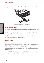
Страница 130: ...to static electricity which can destroy data Figure 8 3 Inserting a SmartMedia Removing CAUTION Do not remove a SmartMedia card while data is being written or read Data could be destroyed Wait for the SmartMedia indicator on the right side of the SmartMedia slot to go out Even if the message Copying on the screen disappears writing to a SmartMedia card might still be in progress 1 Right click righ...

Страница 131: ...or expose it to liquids or let it get dirty 5 After using SmartMedia return it to its case SD Cards The computer is equipped with an SD Card slot that can accommodate Secure Digital flash memory cards with capacities of 8 MB 16 MB 32 MB 64 MB and 128 MB SD cards let you easily transfer data from devices such as digital cameras and Personal Digital Assistants that use SD Card flash memory The cards...

Страница 132: ...e a firm connection Figure 8 5 Inserting an SD card Removing an SD card To remove an SD card follow the steps below 1 Click the Safety Remove Hardware icon on the Task Bar 2 Point to SD card and click 3 Push in the card and release it to pop the card out slightly 4 Grasp the card and remove it Figure 8 6 Inserting an SD card SD Cards ...

Страница 133: ...rs of liquid 7 After using an SD card return it to its case 8 Do not touch the metal part or expose it to liquids or let it get dirty Memory expansion You can install additional memory in the computer s memory module socket to increase the amount of RAM This section describes how to install and remove a memory module CAUTION Do not try to install or remove a memory module under the following condi...

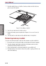
Страница 134: ... Remove two screws securing the memory module socket cover 5 Slide your fingernail or a thin object under the cover and lift it off Figure 8 7 Removing the memory module socket cover 6 Fit the module s connectors into the computer s connectors at about a 45 degree angle and press the module carefully to ensure a firm connection CAUTION Do not touch the connectors on the memory module or on the com...

Страница 135: ...e power on and make sure the added memory is recognized Removing memory module To remove the memory module make sure the computer is in boot mode then 1 Be sure the power is off and all cables are disconnected from the computer 2 Turn the computer upside down and remove the battery and two screws securing the memory module socket cover 3 Slide your fingernail or a thin object under the cover and l...

Страница 136: ...ttery pack Additional battery pack You can increase the portability of the computer with additional battery packs If you re away from an AC power source and your battery runs low you can replace it with a freshly charged battery See Chapter 6 Power and Power Up Modes Additional AC adaptor If you frequently transport the computer between different sites such as your home and office purchasing an AC...

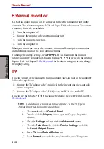
Страница 137: ...ard for details on using hot keys to change the display setting TV You can connect a television set to the line out and video out jack on the computer Follow the steps below 1 Connect the TV adaptor cable s mini jack to the line out and video out jack on the computer 2 Connect the TV adaptor cable s RCA jack to the RCA jack on the TV You can use the hotkeys Fn F5 to change the display device Refer...

Страница 138: ...ransfering data through an IEEE1394 hub do not connect or disconnect other devices from the hub during data transfer There is a likeli hood that data will be damaged Connect all devices to the hub before you turn on the computer s power Connecting 1 Make sure the connectors are properly aligned and plug the i LINK IEEE1394 cable into the computer 2 Plug the other end of the cable into the device N...

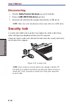
Страница 139: ... lock A security lock enables you to anchor your computer to a desk or other heavy object to help prevent unauthorized removal of the computer Attach one end of a cable to the desk and the other end to the security lock slot on the left side of the computer Figure 8 10 Security lock NOTE If you connect a security cable to the computer when the PC Card lock is set to the lock position you will not ...

Страница 140: ... using PrtSc The questions and procedures offered in this chapter are meant as a guide they are not definitive problem solving techniques Many problems can be solved simply but a few may require help from your dealer If you find you need to consult your dealer or others be prepared to describe the problem in as much detail as possible Preliminary checklist Consider the simplest solution first The ...

Страница 141: ...rint a copy of the screen if you have a printer attached Look up the messages in the software and operating system documentation Check that all connecting cables are correctly and firmly attached Loose cables can cause erroneous or intermittent signals Do any indicators light Which ones What color are they Do they stay on or blink Write down what you see Do you hear any beeps How many Are they lon...

Страница 142: ...discusses problems caused by your computer s hardware or attached peripherals Basic problems may occur in the following areas System start up PCcard Self test Infrared port Power Pointing device Password USB Hotkeys Memoryexpansion Keyboard Sound system LCDpanel Monitor Hard disk drive i LINK IEEE1394 DVD ROMdrive Modem CD RW DVD ROMdrive LAN SmartMediaslot WirelessLAN SDcard Bluetooth System star...

Страница 143: ...haracters appear on the screen and the system does not function normally The screen displays an error message Turn off the computer and check all cable connections as well as PC Card and memory module connections If the test fails again contact your dealer Power When the computer is not plugged into an AC outlet the battery pack is the primary power source However your computer has a number of oth...

Страница 144: ...l does not start or if it starts but shuts down quickly contact your dealer AC power If you have trouble turning on the computer with the AC adaptor connected check the DC IN indicator Refer to Chapter 6 Power and Power Up Modes for more information Problem Procedure AC adaptordoesn t Check the connections Make sure the cord powerthecomputer is firmly connected to the computer and a DC IN indicato...

Страница 145: ...ng power Plug in an appliance gloworange and see if it works If it doesn t try another power source Check whether the battery is hot or cold If the battery is too hot or too cold it will not charge properly Let it reach room temperature Unplug the AC adaptor and remove the battery to make sure the terminals are clean If necessary wipe them with a soft dry cloth dipped in alcohol Connect the AC ada...

Страница 146: ...keys do not work While Windows is starting only Fn F5 works Other hotkeys do not work If you are still unable to use the hotkeys consult yourdealer Keyboard Keyboard problems can be caused by your setup configuration For more informa tion refer to Chapter 5 The Keyboard Problem Procedure Some letter keys Check that the numeric keypad overlay is not producenumbers selected Press Fn F10 and try typi...

Страница 147: ...ly with a clean dry cloth If markings remain use LCD cleaner Be sure to let the LCD dry before closing it Problemsabove Refer to your software s documentation to remainunresolved determine if the software is causing the orotherproblems difficulty occur Contact your dealer if the problems continue Hard disk drive Problem Procedure Computerdoesnot Check if a diskette is in the diskette drive If a bo...

Страница 148: ...ly a CD DVD in the drive closed Press gently until it clicks into place Open the drawer and make sure the CD DVD is properly seated It should lie flat with the label facingup A foreign object in the drawer could block laser light from reading the CD DVD Make sure there is no obstruction Remove any foreign object Check whether the CD DVD is dirty If it is wipe it with a clean cloth dipped in water ...

Страница 149: ...information refer to Chapter 4 Operating Basics Problem Procedure You cannot access Make sure the drive s drawer is securely a CD DVD in the drive closed Press gently until it clicks into place Open the drawer and make sure the CD DVD is properly seated It should lie flat with the label facingup A foreign object in the drawer could block laser light from reading the CD DVD Make sure there is no ob...

Страница 150: ...that on the CD RW DVD ROM drive Region codes are listed in the Drives section in Chapter 2 The Grand Tour Cannot write correctly If you have trouble writing make sure you are observingthefollowingprecautions Use only media recommended by TOSHIBA Do not use the mouse or keyboard during writing Use only the software supplied with the computerforrecording Do not run or start other software during wri...

Страница 151: ...You cannot write Make sure the card is not write protected to a SmartMedia card Delete any unneeded files on the SmartMedia and try again Try another SmartMedia card If you can access this card the original card not the SmartMedia slot is probably causing the problem You cannot read Make sure the target file is on the SmartMedia a file card inserted in the slot TheSmartMediacard Format the SmartMe...

Страница 152: ...ure the card is not write protected to an SD card You cannot read Make sure the target file is on the SD a file Card inserted in the slot If problems persist contact your dealer PC Card Refer also to Chapter 8 Optional Devices Problem Procedure PCCard Reseat the PC Card to make sure it is erroroccurs firmlyconnected Make sure the connection between the external device and the card is firm Check th...

Страница 153: ...in this chapter and to your mouse documentation Touch Pad Problem Procedure On screenpointer The system might be busy If the pointer is does not respond to shaped as an hourglass wait for it to resume TouchPadoperation its normal shape and try again to move it Double tapping Try changing the double click speed setting in does not work the mouse control utility 1 Open the Control Panel select the M...

Страница 154: ...ry again to move it Make sure the mouse is properly connected to the USB port Double clicking Try changing the double click speed setting in the does not work mouse control utility 1 Open the Control Panel select the Mouse icon and press Enter 2 Click the Buttons tab 3 Set the double click speed as instructed and click OK Themousepointer Try changing the speed setting in the mouse moves too fast o...

Страница 155: ...drivers are properly installed Refer to your Windows XP documenta tion for information on checking the drivers If problems persist contact your dealer Memory expansion Refer also to Chapter 8 Optional Devices for information on installing memory modules Problem Procedure Thefollowingmessage Make sure the memory module installed in the is displayed expansion slot is compatible with the computer Ple...

Страница 156: ... secure If problems persist contact your dealer Monitor Refer also to Chapter 8 Optional Devices and to your monitor s documentation Problem Procedure Monitor does not Make sure that the external monitor s power turn on switch is on Confirm that the external monitor s power cable is plugged into a working power outlet No display Try adjusting the contrast and brightness controls on the external mo...

Страница 157: ... drivers Open the Windows Control Panel and double click the Add New Hardware icon Follow the on screen directions Restart Windows If problems persist contact your dealer Modem Refer to the online help files for Appendix C and D Problem Procedure Communication Make sure the computer s internal modem softwarecan t settings are correct Refer to Phone and Modem initialize modem Properties in the Cont...

Страница 158: ...r will automatically cut off cut off unexpectedly communication when connection with the carrier is not successful for a set time interval Try lengthening this time interval A CONNECT display Check the error control setting in your is quickly replaced by communications application NO CARRIER You can also use the AT N command Refer to the online help files for Appendix C AT Com mands Characterdispl...

Страница 159: ... AC adaptor is connected The does not work Wake up on LAN function consumes power even when the system is off If problems persist consult your LAN administra tor Wireless LAN If the following procedures do not restore LAN access consult your LAN adminis trator Formoreinformationonwirelesscommunication refertoChapter4 Operat ing Basics Problem Procedure Cannot access Make sure the computer s wirele...

Страница 160: ...experience may be related to software or the operating system it is important to investigate other sources of assistance first Before contacting TOSHIBA trythefollowing Review troubleshooting sections in the documentation for software and peripheraldevices If a problem occurs when you are running software applications consult the software documentation for troubleshooting suggestions Call the soft...

Страница 161: ...lifornia92618 USA InEurope Germany Austria TOSHIBAEurope I E GmbH Geschäftsbereich Deutschland Österreich Hammfelddamm8 D 41460Neuss Germany France TOSHIBASystèmsFranceS A 7 RueAmpèreB P 131 92804PuteauxCedex Netherlands TOSHIBAInformationSystems BeneluxB V RiviumBoulevard 412909LKCapellea dIJssel Spain TOSHIBAInformationSystems ESPAÑA ParqueEmpresarialSanFernando EdificioEuropa la Planta Escalera...

Страница 162: ...meters Environmental Requirements Ambient Relative Conditions temperature humidity Operating 5 C 41 F to 35 C 95 F 20 to 80 Non operating 20 C 4 F to 65 C 149 F 10 to 95 Thermal Gradient 20 C per hour maximum Wet bulb temperature 26 C maximum Conditions Altitude from sea level Operating 60 to 3 000 meters Non operating 60 to 10 000 meters maximum Power Requirements AC adaptor 100 240 volts AC 50 o...

Страница 163: ...l 103 212A Fax ITU T Rec V 17 V 29 V 27ter FormerCCITT V 21ch2 Communication Data transmission and reception speed 300 1200 2400 4800 7200 9600 12000 14400 16800 19200 21600 24000 26400 28800 31200 33600bps DatareceptiononlywithV 90 28000 29333 30666 32000 33333 34666 36000 37333 38666 40000 41333 42666 44000 45333 46666 48000 49333 50666 52000 53333 54666 56000bps Fax 2400 4800 7200 9600 12000 14...

Страница 164: ...supto1024 horizontaland768verticalpixelsor1600horizontaland1200verticalpixels A high resolution external monitor connected to the computer can display up to 2048 horizontal and 1536 vertical pixels at 16 M colors The display controller also controls the video mode which uses industry standard rules to govern the screen resolution and the maximum number of colors that can be displayed on screen Sof...

Страница 165: ...ls Table1 Video modes VGA Video Type Resolution Character LCD CRT Scanning mode matrix colors colors frequency pels Vertical Hz 0 1 VGA 40 x 25 8 x 8 16 of 256K 16 of 256K 70 Text Characters 2 3 VGA 80 x 25 8 x 8 16 of 256K 16 of 256K 70 Text Characters 0 1 VGA 40 x 25 8 x 14 16 of 256K 16 of 256K 70 Text Characters 2 3 VGA 80 x 25 8 x 14 16 of 256K 16 of 256K 70 Text Characters 0 1 VGA 40 x 25 9 ...

Страница 166: ... 8 x 8 16 of 256K 16 of 256K 70 Grph Pels E VGA 640 x 200 8 x 8 16 of 256K 16 of 256K 70 Grph Pels F VGA 640 x 350 8 x 14 Mono Mono 70 Grph Pels 10 VGA 640 x 350 8 x 14 16 of 256K 16 of 256K 70 Grph Pels 11 VGA 640 x 480 8 x 16 2 of 256K 2 of 256K 60 Grph Pels 12 VGA 640 x 480 8 x 16 16 of 256K 16 of 256K 60 Grph Pels 13 VGA 320 x 200 8 x 8 256 of 256K 256 of 256K 70 Grph Pels ...

Страница 167: ...40 x 480 256 256K 256 256K 60 75 85 100 800 x 600 256 256K 256 256K 60 75 85 100 1024 x 768 256 256K 256 256K 60 75 85 100 1280 x 1024 256 256K 256 256K 60 Virtual 75 85 100 1600 x 1200 256 256K 256 256K 60 Virtual 75 85 100 1920 x 1440 256 256K 256 256K 60 Virtual 75 2048 x 1536 256 256K 256 256K 60 Virtual 75 ...

Страница 168: ...uency Hz 640 x 480 64K 64K 64K 64K 60 75 85 100 800 x 600 64K 64K 64K 64K 60 75 85 100 1024 x 768 64K 64K 64K 64K 60 75 85 100 1280 x 1024 64K 64K 64K 64K 60 Virtual 75 85 100 1600 x 1200 64K 64K 64K 64K 60 Virtual 75 85 100 1920 x 1440 64K 64K 64K 64K 60 Virtual 75 2048 x 1536 64K 64K 64K 64K 60 Virtual 75 ...

Страница 169: ...requency Hz 640 x 480 16M 16M 16M 16M 60 75 85 100 800 x 600 16M 16M 16M 16M 60 75 85 100 1024 x 768 16M 16M 16M 16M 60 75 85 100 1280 x 1024 16M 16M 16M 16M 60 Virtual 75 85 100 1600 x 1200 16M 16M 16M 16M 60 Virtual 75 85 100 1920 x 1440 16M 16M 16M 16M 60 Virtual 75 2048 x 1536 16M 16M 16M 16M 60 Virtual ...

Страница 170: ...40 x 480 256 256K 256 256K 60 75 85 100 800 x 600 256 256K 256 256K 60 75 85 100 1024 x 768 256 256K 256 256K 60 75 85 100 1280 x 1024 256 256K 256 256K 60 75 85 100 1600 x 1200 256 256K 256 256K 60 75 85 100 1920 x 1440 256 256K 256 256K 60 Virtual 75 2048 x 1536 256 256K 256 256K 60 Virtual Appendix B ...

Страница 171: ...rs colors frequency Hz 640 x 480 64K 64K 64K 64K 60 75 85 100 800 x 600 64K 64K 64K 64K 60 75 85 100 1024 x 768 64K 64K 64K 64K 60 75 85 100 1280 x 1024 64K 64K 64K 64K 60 75 85 100 1600 x 1200 64K 64K 64K 64K 60 75 85 100 1920 x 1440 64K 64K 64K 64K 60 Virtual 75 2048 x 1536 64K 64K 64K 64K 60 Virtual ...

Страница 172: ...equency Hz 640 x 480 16M 16M 16M 16M 60 75 85 100 800 x 600 16M 16M 16M 16M 60 75 85 100 1024 x 768 16M 16M 16M 16M 60 75 85 100 1280 x 1024 16M 16M 16M 16M 60 75 85 100 1600 x 1200 16M 16M 16M 16M 60 75 85 100 1920 x 1440 16M 16M 16M 16M 60 Virtual 75 2048 x 1536 16M 16M 16M 16M 60 Virtual Appendix B ...

Страница 173: ...User s Manual B 10 A PPENDIX B ...

Страница 174: ...epted by the modem are described in this section any entry other than those listed results in an error Escape sequence The escape sequence allows the modem to exit data mode and enter on line command mode While in on line command mode you can communicate directly to your modem using AT commands Once you finish you can return to data mode using the ATO command A pause the length of which is set by ...

Страница 175: ...e ATD command Any digit or symbol 0 9 A B C D may be dialed as touch tone digits Characters such as spaces hyphens and parentheses do not count They are ignored by the modem but you may want to include them to make the number and modifiers easier to read The following may be used as phone number modifiers P Pulsedialing T Touch tone dialing default Pause during dialing Pause for time specified in ...

Страница 176: ...E0 Disables echo to the computer E1 Enables echo to the computer default Result Codes OK n 0 1 ERROR Otherwise Hn Hook control This command instructs the modem to go on hook to disconnect a call or off hook to make the phone line busy H0 Modem goes on hook default H1 Modem goes off hook Result Codes OK n 0 1 ERROR Otherwise In Request ID information This command displays product information about ...

Страница 177: ...ression Result V 42bis Estimated Noise Level 233 Receive Signal Power Level dBm 16 Transmit Signal Power Level dBm 18 Round Trip Delay msec 20 Near Echo Level dBm 30 Far Echo Level dBm 74 Transmit Frame Count 0 Transmit Frame Error Count 0 Receive Frame Count 0 Receive Frame Error Count 0 Retrain by Local Modem 0 Retrain by Remote Modem 0 Rate Renegotiation by Local Modem 0 Rate Renegotiation by R...

Страница 178: ... on until the modem detects the carrier signal default M2 The speaker is always on when modem is off hook M3 The speaker is on until the carrier is detected except when dialing Result Codes OK n 0 1 2 3 ERROR Otherwise Nn Modulation handshake This command controls whether or not the local modem performs a negotiated handshake at connection time with the remote modem when the communication speed of...

Страница 179: ...rate renegotiation before returning to on line data mode Result Codes OK n 0 1 3 ERROR Otherwise P Select pulse dialing This command configures the modem for pulse non touch tone dialing Dialed digits are pulsed until a T command or dial modifier is received Tone dial is the default setting Qn Result code control Result codes are informational messages sent from the modem and displayed on your mon...

Страница 180: ...des as text default Result Codes OK n 0 1 ERROR Otherwise Xn Result code selection call progress monitoring This command selects which result codes will be used by the modem Command Dialtone Busysignal Supported detect detect Result Code X0 Disabled Disabled OK CONNECT RING NO CARRIER ERROR X1 Disabled Disabled OK RING NO CARRIER ERROR CONNECT RATE X2 Enabled Disabled OK RING NO CARRIER ERROR NODI...

Страница 181: ...ion of a dial tone and disconnects the call if the dial tone is not detected within 10 seconds Busy tone detect Disabled The modem ignores any busy tones it receives Enabled The modem monitors for busy tones ResultCodes OK n 0 1 2 3 4 5 ERROR Otherwise Zn Recall stored profile The modem performs a soft reset and restores recalls the configura tion profile according to the parameter supplied If no ...

Страница 182: ...nd changes to the DTR signal D0 Ignore The modem ignores the true status of DTR and treats it as always on This should only be used if your communica tion software does not provide DTR to the modem D1 If the DTR signal is not detected while in on line data mode the modem enters command mode issues an OK result code and remains connected D2 If the DTR signal is not detected while in on line data mo...

Страница 183: ...therwise Kn Local flow control selection K0 Disables flow control K3 EnablesCTS RTSflowcontrol default K4 EnablesXON XOFFflowcontrol Result Codes OK n 0 3 4 ERROR Otherwise Pn Select Pulse Dial Make Break Ratio P0 Selects 39 61 make break ratio at 10 pulses per second P1 Selects 33 67 make break ratio at 10 pulses per second P2 Selects 33 67 make break ratio at 20 pulses per second Result Codes OK...

Страница 184: ...ommand is used to store up to four dialing strings in the modem s nonvolatile memory for later dialing The format for the command is Zn stored number where n is the location 0 3 to which the number should be written The ATDS n command dials using the string stored in location n Result codes OK n 0 1 2 3 ERROR Otherwise Nn Error control mode selection This command determines the type of error contr...

Страница 185: ...e as Q5 N4 V 42 or disconnect The modem attempts to connect in V 42 error control mode If this fails the modem disconnects N5 V 42 MNPorBuffer sameas N3 N7 V 42 MNPorBuffer sameas N3 Result Codes OK n 0 1 2 3 4 5 7 ERROR Otherwise Qn Local flow control selection Q0 Disableflowcontrol Q1 XON XOFFsoftwareflowcontrol Q3 CTS RTStoDTE default Result Codes OK n 0 1 3 ERROR Otherwise Vn Protocol result c...

Страница 186: ...code appears in countries regions that do not require blacklisting Cn Data compression control This command determines the operation of V 42bis and MNP class 5 data compression On line changes do not take effect until a discon nect occurs first C0 V 42bis MNP 5 disabled No data compression C3 V 42bis MNP 5 enabled Data compression enabled default Result Codes OK n 0 3 ERROR Otherwise ...

Страница 187: ...User s Guide C 14 A PPENDIX C ...

Страница 188: ...ually when the modem is in command mode This chapter describes the settings for each S register NOTE Some registers vary from one country region to another S register values The format for displaying the value of an S register is ATSn where n is the register number After you type in the register press Enter The format for modifying the value of an S register is ATSn r where n is the register numbe...

Страница 189: ...mode when on line Values greater than 127 disable the escape sequence Range 0 255 ASCII decimal Default 43 Units ASCII S3 Command line termination character user defined This register determines the ASCII values as the carriage return character This character is used to end command lines and result codes Range 0 127 ASCII decimal Default 13 carriagereturn Units ASCII S4 Response formatting charact...

Страница 190: ...t digit of the telephone number The modem always pauses for a minimum of three seconds even if the value of S6 is less that three seconds The wait for dial tone call progress feature W dial modifier in the dial string will override the value in register S6 This operation however may be affected by some ATX options according to country region restric tions In some regions S6 will set dial tone dete...

Страница 191: ...g speed This register determines the dialing speed which is prefixed for each country region Range 50 255 Default 95 Units milliseconds S12 Escape guard time This register sets the value in 20 ms increments for the required pause after the escape sequence default 1 s Range 0 255 Default 50 Units 20 milliseconds S37 Dial line rate S37 0 default maximummodemspeed S37 1 reserved S37 2 1200 75bps S37 ...

Страница 192: ... connected to line RING 2 A ring signal has been detected NOCARRIER 3 Modem lost carrier signal or does not detect carrier signal or does not detect answer tone ERROR 4 Invalidcommand CONNECT1200EC 1 5 Connection at 1200 bps NODIALTONE 6 No dial tone detected BUSY 7 Busy signal detected NOANSWER 8 No quiet answer CONNECT2400EC 1 10 Connection at 2400 bps CONNECT4800EC 1 11 Connection at 4800 bps C...

Страница 193: ...s DTE rate CONNECT57600EC 1 18 Connection at 57600 bps DTE rate CONNECT115200EC 1 87 Connection at 115200 bps DTE rate DELAYED 2 88 Delay is in effect for the dialed number BLACKLISTED 2 89 Dialed number is blacklisted BLACKLISTFULL 2 90 Blacklistisfull 1 EC only appears when the Extended Result Codes configuration option is enabled EC is replaced by one of the following symbols depending upon the...

Страница 194: ...y considerably Therefore many users will experience throughput in the range of 28 50Kbps under normal telephone line conditions Upstream data flows at the V 34 rate NOTE V 90 rates can be achieved only when one V 90 capable host modem is connected to another The TOSHIBA Internal modem will select automatically V 34 if the remote modem lacks V 90 capability or if a combination of network and or pho...

Страница 195: ... at 28000 bps 101 CONNECT 29333 EC Connection at 29333 bps 102 CONNECT 30666 EC Connection at 30666 bps 103 CONNECT 33333 EC Connection at 33333 bps 104 CONNECT 34666 EC Connection at 34666 bps 105 CONNECT 37333 EC Connection at 37333 bps 106 CONNECT 38666 EC Connection at 38666 bps 107 CONNECT 41333 EC Connection at 41333 bps 108 CONNECT 42666 EC Connection at 42666 bps 109 CONNECT 45333 EC Conne...

Страница 196: ...g symbols depending on the error control method used V42bis V 42 error control and V 42bis data compression V42 V 42 error control only NoEC No error control protocol AT Command V90 V 90 Dial Line Rate V90 sets the maximum V 90 downstream that the modem attempts to connect V90 0 V 90 disabled V90 1 V 90 enabled automatic speed selection maximum modem speed default Appendix E ...

Страница 197: ...User s Manual E 4 A PPENDIX E ...

Страница 198: ...he internal modem remove the battery pack Refer to chapter 6 for details on removing the battery pack Installing the modem board and jack To install the modem board and jack follow the steps below 1 Turn the computer upside down 2 Remove two screws securing the cover 3 Slip your fingernail or a narrow object into a notch under the cover and lift off the cover 4 Fit the modem jack into its slot 5 S...

Страница 199: ...he internal modem To remove the internal modem 1 Remove the battery 2 Remove the modem cover 3 Remove the modem board 4 Remove the modem jack 5 Secure the modem cover 6 Install the battery pack Refer to the installation procedures for details ...

Страница 200: ...amingovermultiplechannels Card specifications Table F 2 Physical specifications Form Factor Mini PCITypeIIIA Color Black for Wireless LAN card Dimensions Weight TemperatureandHumidity Operation 0 to 55 C Maximum humidity 95 Transit 20 to 70 C 15 to 95 no condensation Storage 10 to 60 C 10 to 90 no condensation Although the card may still operate in the range of 20 to 70 C operation outside the ran...

Страница 201: ...otocol Acknowledgment ACK Data Rate High 11 Mb s Medium 5 5 Mb s Standard 2 Mb s Low 1 Mb s The cards use an automatic Transmit Rate Select mechanism Radio characteristics Radio characteristics of Wireless LAN cards may vary according to Country region where the product was purchased Type of product Wireless communication is often subject to local radio regulations Although Wireless LAN networking...

Страница 202: ...stances NOTE The range values listed in Table F 5 are typical distances as measured at the TOSHIBA Wireless LAN laboratories These values provide rule of thumb guides They may vary according to the actual radio conditions at the location where the Wireless LAN product is installed The range of your Wireless devices can be affected when the antennas are placed near metal surfaces and solid high den...

Страница 203: ...47 9 2452 10 2457 11 2462 Factory set default channels When installing Wireless LAN cards the channel configuration is managed as follows For Wireless clients that operate in a Wireless LAN Infrastructure the Wireless LAN card will automatically start operation at the channel identified by the Wireless LAN Access Point When roaming between different access points the station can dynamically switch...

Страница 204: ...ding on country region s power standards Certification agencies U S and Canada UL listed and CSA certified No 18 AWG Type SVT or SPT 2 two conductor Europe Austria OVE Italy IMQ Belgium CEBEC The Netherlands KEMA Denmark DEMKO Norway NEMKO Finland SETI Sweden SEMKO France UTE Switzerland SEV Germany VDE United Kingdom BSI Australia AS Japan DENANHO In Europe power cords must be VDE type H05VVH2 F ...

Страница 205: ...llowing illustrations show the plug shapes for the U S A and Canada the United Kingdom Australia and Europe USA and Canada United Kingdom Australia Europe BS approved UL approved CSA approved AS approved Approved by the appropriate agency ...

Страница 206: ...urrent DDC display data channel DDR double data rate DMA direct memory access DOS disk operating system DVD digital versatile disk ECP extended capabilities port EGA enhanced graphics adaptor FDD floppy disk drive FIR fast infrared HDD hard disk drive IDE integrated drive electronics I O input output IrDA Infrared Data Association IRQ interrupt request KB kilobyte LCD liquid crystal display LED li...

Страница 207: ...rt for asynchronous asynchronous Lacking regular time relationship As applied to computer communications asynchronous refers to the method of transmitting data that does not require a steady stream of bits to be transmitted at regular time intervals Abbreviationscontinued SVGA super video graphics adaptor TFT thin filmtransistor UART universal asynchronous receiver transmitter USB Universal Serial...

Страница 208: ...l card containing electronic components called chips which perform a specific function or increase the capabilities of the system boot Short for bootstrap A program that starts or restarts the computer The program reads instructions from a storage device into the computer s memory bps Bits per second Typically used to describe the data transmission speed of a modem buffer The portion of the comput...

Страница 209: ...er number punctuation mark or symbol used by the computer Also synonymous with byte chassis The frame containing the computer chip A small semiconductor contain ing computer logic and circuitry for processing memory input output functions and controlling other chips CMOS Complementary Metal Oxide Semiconductor An electronic circuit fabricated on a silicon wafer that requires very little power Inte...

Страница 210: ...en sive math calculations CPS Characters Per Second Typi cally used to indicate the transmission speed of a printer CPU Central Processing Unit The portion of the computer that interprets and executes instructions CRT Cathode Ray Tube A vacuum tube in which beams projected on a fluorescent screen producing luminous spots An example is the television set cursor A small blinking rectangle or line th...

Страница 211: ...f a computer system or applica tion Computer system documentation typically includes procedural and tutorial information as well as system functions DOS Disk Operating System See operating system driver A software program generally part of the operating system that controls a specific piece of hardware frequently a peripheral device such as a printer or mouse E echo To send back a reflection of th...

Страница 212: ...drive FDD An electro mechanical device that reads and writes to floppy disks See also diskette Fn esse A TOSHIBA utility that lets you assign functions to hotkeys folder An icon in Windows used to store documents or other folders format The process of readying a blank disk for its first use Formatting establishes the structure of the disk that the operating system expects before it writes files or...

Страница 213: ...indows an icon represents an object that the user can manipulate iLINK IEEE1394 Thisportenables high speed data transfer directly from external devices such as digital video cameras infrared port A cableless communi cations port capable of using infrared signals to send serial data input The data or instructions you provide to a computer communication device or other peripheral device from the key...

Страница 214: ...megabyte MB A unit of data storage equal to 1024 kilobytes See also kilobyte megahertz A unit of wave frequency that equals 1 million cycles per second See also hertz menu A software interface that displays a list of options on the screen Also called a screen menu J jumper Asmallcliporwirethat allows you to change the hardware characteristics by electrically connect ing two points of a circuit K K...

Страница 215: ...hrough the serial port of internal modem or 4 stored on some magnetic media microprocessor microprocessor A hardware compo nent contained in a single integrated circuit that carries out instructions Also called the central processing unit CPU one of the main parts of the computer mode A method of operation for example the boot mode or the resume mode monitor A device that uses rows and columns of ...

Страница 216: ... peripheral component interconnect An industry standard 32 bit bus peripheral device An I O device that is external to the central processor and or main memory such as a printer or a mouse pixel A picture element The smallest dot that can be made on a display or printer Also called a pel plugandplay Acapabilitywith Windows that enables the system to automatically recognize connections of external ...

Страница 217: ... Key combinations that emulate keys on the IBM keyboard change some configuration options stop program execution and access the numeric keypad overlay Radio frequency interference shield R Radiofrequencyinterference RFI shield A metal shield enclosing the printed circuit boards of the printer or computer to prevent radio and TV interference All computer equipment generates radio frequency signals ...

Страница 218: ...em disk Also called an operating system disk T terminal Atypewriter likekeyboard and CRT display screen connected to the computer for data input output touchpad Apointingdeviceinte grated into the TOSHIBA computer palmrest write protection TTL Transistor transistor logic A logic circuit design that uses switch ing transistors for gates and storage U Universal Serial Bus This serial interface lets ...

Страница 219: ...Glossary 14 G G G G G L O S S A R Y L O S S A R Y L O S S A R Y L O S S A R Y L O S S A R Y Glossary ...

Страница 220: ... 4 3 view 2 13 E Environment 3 1 Equipmentchecklist 1 1 Equipment setup general conditions 3 2 placement 3 2 A AC adaptor 1 3 additional 1 10 8 11 connecting 3 5 DCIN15Vport 2 6 view 2 14 ASCII characters 5 9 Audio video control buttons 1 5 2 2 4 8 B Battery automatic hibernation 1 8 charging 6 6 extendinglife 6 8 indicator 2 10 6 2 location 2 7 monitoring capacity 6 7 realtimeclock 1 3 6 4 safety...

Страница 221: ... 1 7 problems 9 8 Headphone jack See Sound system Heat dispersal See Cooling Hibernation 1 8 automatic 1 7 setting 3 8 Hot keys 1 7 display brightness decrease 5 5 display brightness increase 5 6 display selection 5 5 hibernation 5 5 instant security 5 4 power save mode 5 4 standby 5 5 wireless setting 5 6 problems 9 7 sound mute 5 4 HWSetup 1 9 7 1 accessing 7 1 boot priority 7 5 general 7 2 Key ...

Страница 222: ...xpansion 1 10 installing 8 9 problems 9 16 removing 8 10 slot 2 7 Microphone jack See Sound system Mode Control button 4 8 Modem 1 6 4 13 connecting 4 15 disconnecting 4 16 jack 2 6 problems 9 18 properties menu 4 14 region selection 4 13 Monitor external 2 3 8 12 problems 9 17 Moving the computer 4 21 N Numeric keypad See Keypad overlay O Overlay See Keypad overlay P Panel power off See Power Pas...

Страница 223: ... 9 4 SmartMediaslot 9 12 sound system 9 17 supportfromTOSHIBA 9 21 system start up 9 3 Touch Pad 9 14 USB 9 16 wirelessLAN 9 20 Processor 1 2 R Real time clock battery See battery RecoveryCD ROM 3 11 Restarting the computer 3 11 S SDCard 1 5 indicator 2 4 installing removing 8 7 location of slot 2 4 problems 9 13 care 8 8 Securitylock 2 3 8 14 Self test See Problems SmartMedia 1 5 care 8 6 indicat...

Страница 224: ...l 1 9 Touch pad 1 4 problems 9 14 using 4 1 Troubleshooting See Problems TV 8 12 U USB 1 4 portlocation 2 3 2 5 problems 9 16 V Video modes Appendix B VideoRAM 1 2 Video outjack 1 5 2 6 Volume control See Sound system W Wirelesscommunication LED 2 1 4 18 setting by hotkeys 5 6 switch 2 2 4 18 Wireless LAN 1 6 problems 9 20 using 4 16 ...

Страница 225: ...User s manual Index 6 ...

Отзывы: