background image

SECTION 1

GENERAL DESCRIPTIONS

1. OPERATING INSTRUCTIONS

Please refer to the owner's manual about the contents.

SECTION 1

GENERAL 

DESCRIPTIONS

Содержание RD-XS34SB

Страница 1: ...HDD DVD VIDEO RECORDER SERVICE MANUAL Feb 2005 S FILE NO 810 200512 RD XS34SB RD XS34SF RD XS34SG DIGITAL VIDEO ...

Страница 2: ...e mat The ground resistance between the ground line and the ground is less than 10W LASER BEAM CAUTION LABEL When the power supply is being turned on you may not remove this laser cautions label If it removes radiation of a laser may be received Manufactured under license from Dolby Laboratories Dolby and the double D symbol are trademarks of Dolby Laboratories DTS and DTS Digital Out are trademar...

Страница 3: ...2 Timer Circuit Diagram 4 4 3 Audio Circuit Diagram 4 4 4 Video Circuit Diagram 4 4 5 MSP Circuit Diagram 4 5 Tuner Unit Circuit Diagram 5 PC BOARDS 5 1 Front Jack PC Board 5 2 Front L PC Board 5 3 Front R PC Board 5 4 Tuner Unit PC Board 5 5 Digital PC Board 5 6 Mother PC Board CONTENTS SECTION 1 GENERAL DESCRIPTIONS 1 OPERATING INSTRUCTIONS 1 REPLACEMENT OF MECHANICAL PARTS 1 1 Cabinet Replaceme...

Страница 4: ...SECTION 1 GENERAL DESCRIPTIONS 1 OPERATING INSTRUCTIONS Please refer to the owner s manual about the contents SECTION 1 GENERAL DESCRIPTIONS ...

Страница 5: ...Parts Fig 1 2 1 2 2 Location of PC Boards Fig 1 2 2 ZG45 FAN RAM1 RAM DRIVE HDD1 HDD UNIT EU05 Mother PC board EU02 Power PC board EU01 Digital PC board EU82 Tuner Unit PC board EU03A Front R PC board EU03B Front L PC board EU55 Front Jack PC board ...

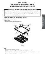
Страница 6: ...r dropping etc always use a magnetized screwdriver in servicing Several kinds of screws are used and some of them need special cautions That is take care of the tapping screws securing molded parts and fine pitch screws used to secure metal parts If they are used improperly the screw holes will be easily damaged and the parts can not be fixed 1 REPLACEMENT OF MECHANICAL PARTS Note There is a ratin...

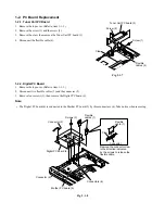
Страница 7: ...t the flexible cable 3 and the connector 4 5 Remove four screws 5 and four dampers 7 then remove the HDD 8 Note After replacing attach the tape 1 to its original position Fig 2 1 2 Dampers 7 Dampers 7 Damper 7 Damper 7 HDD 8 Tape 1 Screws 5 Screws 5 Screws 2 Screws 2 Flexible cable 3 Connector 4 HDD bracket 6 ...

Страница 8: ... 3 Disconnect two connectors 2 and two flexible cables 3 4 Remove two screws 4 and four claws then remove the front panel 5 Note After replacing attach the tape 1 to its original position Fig 2 1 3 Flexible cables 3 Connector 2 Connector 2 Tapes 1 Screws 4 Front panel 5 Claws Claw Claw ...

Страница 9: ...and the connector 3 4 Remove three screws 4 then remove the RAM drive 5 5 Remove four screws 6 then remove the RAM drive bracket 7 Note After replacing attach the tape 1 to its original position Fig 2 1 4 Flexible cable 2 Connector 3 Screw 4 Screw 4 Screw 4 Tapes 1 Tape 1 RAM drive 5 Screws 6 Screws 6 RAM drive bracket 7 ...

Страница 10: ... 7 Note After replacing attach the tape 1 to its original position Fig 2 1 5 1 1 6 Fan 1 Remove the top cover Refer to item 1 1 1 2 Peel off the tape 1 3 Remove the connector 2 4 Remove two screws 3 then remove thefan 4 Note After replacing attach the tape 1 to its original position Screw 2 Screws 4 Screws 3 Tape 1 Screws 6 Rear panel 5 Fan 7 Hexagonal nut Claw Claw Screws 3 Connector 2 Fan 4 Tape...

Страница 11: ... the top cover Refer to item 1 1 1 2 Disconnect two flexible cables 1 and the connector 2 3 Remove four screws 3 then remove the Digital PC board 4 Note The Digital PC board 4 is connected to the Mother PC board 5 by three connectors 6 Take notice when removing Fig 2 1 8 Connector 2 Connector 6 Screws 3 Digital PC board 4 Connectors 6 Flexible cables 1 Mother PC board 5 A A Flexible cable 1 Connec...

Страница 12: ...er to item 1 1 5 3 Remove the Tuner Unit PC board Refer to item 1 2 1 4 Remove the Digital PC board Refer to item 1 2 2 5 Disconnect the flexible cable 1 and the connector 2 6 Remove six screws 3 then remove the Mother PC board 4 Fig 2 1 9 Screws 3 Connector 2 Flexible cable 1 Mother PC board 4 ...

Страница 13: ...ace only with the same or equivalent type 1 Remove the top cover Refer to item 1 1 1 2 Disconnect three connectors 1 and the connector 2 3 Remove three screws 3 and the screw 4 then remove the Power PC board 5 Fig 2 1 10 Connector 1 Connectors 1 Connector 2 Screws 3 Power PC board 5 Screw 4 ...

Страница 14: ...Jack PC board 7 6 Remove four screws 8 then remove the Front L PC board 9 Note After replacing attach the tape 1 to its original position Fig 2 1 11 Screws 2 Screws 4 Tapes 1 Screws 8 Screws 6 Stay 3 Front L PC board 9 Front R PC board 5 Front panel Front Jack PC board 7 Stay Wire Tray door Front L PC board Front R PC board Front Jack PC board Fasten with the tape Fig 2 1 12 Note Fasten with the t...

Страница 15: ...ete return the wiring to its original state by using the diagram below as a reference Front panel HDD RAM drive W056 W003 W100 W003 Power PC board Mother PC board Tuner Unit PC board Digital PC board W004 W101 Fan W051 W052 W055 Tape Flexible cable Fig 2 2 1 ...

Страница 16: ... processing be sure to include the model number and description ABBREVIATIONS Integrated Circuit IC Capacitor Cap Capacitance Tolerance for Nominal Capacitance more than 10pF P 100 0 Symbol Tolerance B 0 1 C 0 25 D 0 5 F 1 G 2 J 5 K 10 M 20 N 30 V 20 10 W 100 10 U 75 10 Q 30 10 T 50 10 Symbol Tolerance X 40 20 Y 150 10 Z 80 20 Ex 10µF J 10µF 5 Symbol Tolerance pF B 0 1 C 0 25 D 0 5 F 1 G 2 Ex 10pF...

Страница 17: ...ZF23 ZF23A ZF23 Power supply cable ZF23 Clamp filter ZF23A Fixed band accessories Note A clamp filter ZF23A is attached to a power cord ZF23 Refer to the figure below for the installation Turn the power supply cable 2 round in the clamp filter Cut the portion in which the fixed band remained ...

Страница 18: ...1 2 Chassis Assembly Fig 4 4 2 EU05 EU01 EU82 EU02 EU03A EU03B ZG01 EU55 ZG20 ZG20A ZG45 W056 W055 W055A ZG50 HDD1 W051 W051A W053 RAM1 W052 ...

Страница 19: ... P000422870 Owners Manual Quick English RD XS34SG c ZF11B P000422610 Owners Manual ST English RD XS34SG c ZF11C P000422620 Owners Manual OP English RD XS34SG c ZF11D P000422630 Owners Manual ST German RD XS34SG c ZF11E P000422640 Owners Manual OP German RD XS34SG c ZF11G P000422650 Owners Manual ST Spanish RD XS34SG c ZF11I P000422660 Owners Manual OP Spanish RD XS34SG a ZF23 79088034 Power Cord U...

Страница 20: ...C1G04HDCKR IC531 P000377900 IC MM1563DFBE IC539 P000401220 IC BU3081FV E2 TRANSISTORS Q301 79050016 Transistor Chip 2SC2712 Y Q302 79050016 Transistor Chip 2SC2712 Y Q303 79050016 Transistor Chip 2SC2712 Y Q304 79050016 Transistor Chip 2SC2712 Y Q305 79050018 Transistor Chip 2SA1162 Y Q306 79050018 Transistor Chip 2SA1162 Y Q307 79050018 Transistor Chip 2SA1162 Y Q308 79050018 Transistor Chip 2SA1...

Страница 21: ...OPT LAF1001 0301F ICB10 P000395150 IC MM1565AFBE ICM01 P000378240 IC MSP3417G ICM02 P000395160 IC PQ05DZ1UJ00H ICW01 P000378260 IC MM1506XNRE ICW02 P000378260 IC MM1506XNRE ICW03 P000378260 IC MM1506XNRE ICW04 P000378270 IC MM1508XNRE ICW05 P000405020 IC TC7W53FU ICW06 P000405020 IC TC7W53FU ICX01 79040382 IC MM1140XFFE ICX02 P000391260 IC MM1568DJBEG ICX03 P000405080 IC XC6209 ICX04 P000395150 IC...

Страница 22: ... D904 79060019 Diode Chip 1SS355 DB01 79060096 Diode Zener MTZJT 7733D DM01 79060019 Diode Chip 1SS355 DW01 79060028 Diode Chip 1SS226 DW03 79060028 Diode Chip 1SS226 DW04 79060019 Diode Chip 1SS355 DW05 79060028 Diode Chip 1SS226 DW06 79060028 Diode Chip 1SS226 DW07 79060028 Diode Chip 1SS226 DW08 79060019 Diode Chip 1SS355 DW09 79060028 Diode Chip 1SS226 DW10 79060028 Diode Chip 1SS226 DW11 7906...

Страница 23: ...05010 Relay ATX209 X700 P000391040 Crystal X701 P000363400 Oscillator Crystal X702 P000395090 Resonator Ceramic FCR4 43MC5AT X703 P000405000 Resonator Ceramic CSBLA500KEC8 BO XM01 P000395100 Resonator Ceramic AT 41 18 432M EU55 P000435080 PC Board Assy Front Jack MISCELLANEOUS J170 P000387300 Jack DV J171 P000402780 Jack 3P 1Y C EU82 P000437420 PC Board Assy Tuner MB01 P0000405090 Tuner TCPM0601PD...

Страница 24: ...SCART socket x 2 at rear VIDEO output 1 0Vp p 75Ω Sync signal negative Pin jack x 1 system 1 at rear SCART socket x 2 at rear S VIDEO input Y 1 0Vp p 75Ω Sync signal negative C 0 286Vp p 75Ω 1 in front Mini DIN4 Pin x 1 system SCART socket x 1 at rear S VIDEO output Y 1 0Vp p 75Ω Sync signal negative C 0 286Vp p 75Ω 1 at rear Mini DIN4 Pin x 1 system SCART socket x 1 at rear COMPONENT output Y PB ...

Страница 25: ...5 C Position Horizontal Clock display 24 hour digital display Clock accuracy Quartz monthly deviation approximately 30 seconds Supplied Accessories Remote control 1 Batteries R03 2 Power cord 1 Coaxial cable 1 Video Audio cable 1 IR control cable 1 OWNER S MANUAL INSTALLATION GUIDE 1 OWNER S MANUAL OPERATIONS 1 Quick Reference 1 The design and specifications may change without prior notice The Ill...

Страница 26: ...Vp p 75Ω Sync signal negative Pin jack x 1 system 1 in front PERITEL socket x 2 at rear VIDEO output 1 0Vp p 75Ω Sync signal negative Pin jack x 1 system 1 at rear PERITEL socket x 2 at rear S VIDEO input Y 1 0Vp p 75Ω Sync signal negative C 0 286Vp p 75Ω 1 in front Mini DIN4 Pin x 1 system PERITEL socket x 1 at rear S VIDEO output Y 1 0Vp p 75Ω Sync signal negative C 0 286Vp p 75Ω 1 at rear Mini ...

Страница 27: ...ition Horizontal Clock display 24 hour digital display Clock accuracy Quartz monthly deviation approximately 30 seconds Supplied Accessories Remote control 1 Batteries R03 2 Power cord 1 Coaxial cable 1 Video Audio cable 1 IR control cable 1 OWNER S MANUAL INSTALLATION GUIDE 1 OWNER S MANUAL OPERATIONS 1 Quick Reference 1 The design and specifications may change without prior notice The Illustrati...

Страница 28: ...put 1 0Vp p 75Ω Sync signal negative Pin jack x 1 system 1 in front SCART socket x 2 at rear VIDEO output 1 0Vp p 75Ω Sync signal negative Pin jack x 1 system 1 at rear SCART socket x 2 at rear S VIDEO input Y 1 0Vp p 75Ω Sync signal negative C 0 286Vp p 75Ω 1 in front Mini DIN4 Pin x 1 system SCART socket x 1 at rear AV2 only S VIDEO output Y 1 0Vp p 75Ω Sync signal negative C 0 286Vp p 75Ω 1 at ...

Страница 29: ...Position Horizontal Clock display 24 hour digital display Clock accuracy Quartz monthly deviation approximately 30 seconds Supplied Accessories Remote control 1 Batteries R03 2 Power cord 1 Coaxial cable 1 Video Audio cable 1 IR control cable 1 OWNER S MANUAL INSTALLATION GUIDE 1 OWNER S MANUAL OPERATIONS 1 Quick Reference 1 The design and specifications may change without prior notice The Illustr...

Страница 30: ...1 1 SHIBAURA 1 CHOME MINATO KU TOKYO 105 8001 JAPAN ...

Страница 31: ...HDD DVD VIDEO RECORDER SERVICE MANUAL Feb 2005 S FILE NO 810 200512 RD XS34SB RD XS34SF RD XS34SG DIGITAL VIDEO ...

Страница 32: ...e mat The ground resistance between the ground line and the ground is less than 10W LASER BEAM CAUTION LABEL When the power supply is being turned on you may not remove this laser cautions label If it removes radiation of a laser may be received Manufactured under license from Dolby Laboratories Dolby and the double D symbol are trademarks of Dolby Laboratories DTS and DTS Digital Out are trademar...

Страница 33: ...2 Timer Circuit Diagram 4 4 3 Audio Circuit Diagram 4 4 4 Video Circuit Diagram 4 4 5 MSP Circuit Diagram 4 5 Tuner Unit Circuit Diagram 5 PC BOARDS 5 1 Front Jack PC Board 5 2 Front L PC Board 5 3 Front R PC Board 5 4 Tuner Unit PC Board 5 5 Digital PC Board 5 6 Mother PC Board CONTENTS SECTION 1 GENERAL DESCRIPTIONS 1 OPERATING INSTRUCTIONS 1 REPLACEMENT OF MECHANICAL PARTS 1 1 Cabinet Replaceme...

Страница 34: ...SECTION 1 GENERAL DESCRIPTIONS 1 OPERATING INSTRUCTIONS Please refer to the owner s manual about the contents SECTION 1 GENERAL DESCRIPTIONS ...

Страница 35: ...Parts Fig 1 2 1 2 2 Location of PC Boards Fig 1 2 2 ZG45 FAN RAM1 RAM DRIVE HDD1 HDD UNIT EU05 Mother PC board EU02 Power PC board EU01 Digital PC board EU82 Tuner Unit PC board EU03A Front R PC board EU03B Front L PC board EU55 Front Jack PC board ...

Страница 36: ...r dropping etc always use a magnetized screwdriver in servicing Several kinds of screws are used and some of them need special cautions That is take care of the tapping screws securing molded parts and fine pitch screws used to secure metal parts If they are used improperly the screw holes will be easily damaged and the parts can not be fixed 1 REPLACEMENT OF MECHANICAL PARTS Note There is a ratin...

Страница 37: ...t the flexible cable 3 and the connector 4 5 Remove four screws 5 and four dampers 7 then remove the HDD 8 Note After replacing attach the tape 1 to its original position Fig 2 1 2 Dampers 7 Dampers 7 Damper 7 Damper 7 HDD 8 Tape 1 Screws 5 Screws 5 Screws 2 Screws 2 Flexible cable 3 Connector 4 HDD bracket 6 ...

Страница 38: ... 3 Disconnect two connectors 2 and two flexible cables 3 4 Remove two screws 4 and four claws then remove the front panel 5 Note After replacing attach the tape 1 to its original position Fig 2 1 3 Flexible cables 3 Connector 2 Connector 2 Tapes 1 Screws 4 Front panel 5 Claws Claw Claw ...

Страница 39: ...and the connector 3 4 Remove three screws 4 then remove the RAM drive 5 5 Remove four screws 6 then remove the RAM drive bracket 7 Note After replacing attach the tape 1 to its original position Fig 2 1 4 Flexible cable 2 Connector 3 Screw 4 Screw 4 Screw 4 Tapes 1 Tape 1 RAM drive 5 Screws 6 Screws 6 RAM drive bracket 7 ...

Страница 40: ... 7 Note After replacing attach the tape 1 to its original position Fig 2 1 5 1 1 6 Fan 1 Remove the top cover Refer to item 1 1 1 2 Peel off the tape 1 3 Remove the connector 2 4 Remove two screws 3 then remove thefan 4 Note After replacing attach the tape 1 to its original position Screw 2 Screws 4 Screws 3 Tape 1 Screws 6 Rear panel 5 Fan 7 Hexagonal nut Claw Claw Screws 3 Connector 2 Fan 4 Tape...

Страница 41: ... the top cover Refer to item 1 1 1 2 Disconnect two flexible cables 1 and the connector 2 3 Remove four screws 3 then remove the Digital PC board 4 Note The Digital PC board 4 is connected to the Mother PC board 5 by three connectors 6 Take notice when removing Fig 2 1 8 Connector 2 Connector 6 Screws 3 Digital PC board 4 Connectors 6 Flexible cables 1 Mother PC board 5 A A Flexible cable 1 Connec...

Страница 42: ...er to item 1 1 5 3 Remove the Tuner Unit PC board Refer to item 1 2 1 4 Remove the Digital PC board Refer to item 1 2 2 5 Disconnect the flexible cable 1 and the connector 2 6 Remove six screws 3 then remove the Mother PC board 4 Fig 2 1 9 Screws 3 Connector 2 Flexible cable 1 Mother PC board 4 ...

Страница 43: ...ace only with the same or equivalent type 1 Remove the top cover Refer to item 1 1 1 2 Disconnect three connectors 1 and the connector 2 3 Remove three screws 3 and the screw 4 then remove the Power PC board 5 Fig 2 1 10 Connector 1 Connectors 1 Connector 2 Screws 3 Power PC board 5 Screw 4 ...

Страница 44: ...Jack PC board 7 6 Remove four screws 8 then remove the Front L PC board 9 Note After replacing attach the tape 1 to its original position Fig 2 1 11 Screws 2 Screws 4 Tapes 1 Screws 8 Screws 6 Stay 3 Front L PC board 9 Front R PC board 5 Front panel Front Jack PC board 7 Stay Wire Tray door Front L PC board Front R PC board Front Jack PC board Fasten with the tape Fig 2 1 12 Note Fasten with the t...

Страница 45: ...ete return the wiring to its original state by using the diagram below as a reference Front panel HDD RAM drive W056 W003 W100 W003 Power PC board Mother PC board Tuner Unit PC board Digital PC board W004 W101 Fan W051 W052 W055 Tape Flexible cable Fig 2 2 1 ...

Страница 46: ... processing be sure to include the model number and description ABBREVIATIONS Integrated Circuit IC Capacitor Cap Capacitance Tolerance for Nominal Capacitance more than 10pF P 100 0 Symbol Tolerance B 0 1 C 0 25 D 0 5 F 1 G 2 J 5 K 10 M 20 N 30 V 20 10 W 100 10 U 75 10 Q 30 10 T 50 10 Symbol Tolerance X 40 20 Y 150 10 Z 80 20 Ex 10µF J 10µF 5 Symbol Tolerance pF B 0 1 C 0 25 D 0 5 F 1 G 2 Ex 10pF...

Страница 47: ...ZF23 ZF23A ZF23 Power supply cable ZF23 Clamp filter ZF23A Fixed band accessories Note A clamp filter ZF23A is attached to a power cord ZF23 Refer to the figure below for the installation Turn the power supply cable 2 round in the clamp filter Cut the portion in which the fixed band remained ...

Страница 48: ...1 2 Chassis Assembly Fig 4 4 2 EU05 EU01 EU82 EU02 EU03A EU03B ZG01 EU55 ZG20 ZG20A ZG45 W056 W055 W055A ZG50 HDD1 W051 W051A W053 RAM1 W052 ...

Страница 49: ... P000422870 Owners Manual Quick English RD XS34SG c ZF11B P000422610 Owners Manual ST English RD XS34SG c ZF11C P000422620 Owners Manual OP English RD XS34SG c ZF11D P000422630 Owners Manual ST German RD XS34SG c ZF11E P000422640 Owners Manual OP German RD XS34SG c ZF11G P000422650 Owners Manual ST Spanish RD XS34SG c ZF11I P000422660 Owners Manual OP Spanish RD XS34SG a ZF23 79088034 Power Cord U...

Страница 50: ...C1G04HDCKR IC531 P000377900 IC MM1563DFBE IC539 P000401220 IC BU3081FV E2 TRANSISTORS Q301 79050016 Transistor Chip 2SC2712 Y Q302 79050016 Transistor Chip 2SC2712 Y Q303 79050016 Transistor Chip 2SC2712 Y Q304 79050016 Transistor Chip 2SC2712 Y Q305 79050018 Transistor Chip 2SA1162 Y Q306 79050018 Transistor Chip 2SA1162 Y Q307 79050018 Transistor Chip 2SA1162 Y Q308 79050018 Transistor Chip 2SA1...

Страница 51: ...OPT LAF1001 0301F ICB10 P000395150 IC MM1565AFBE ICM01 P000378240 IC MSP3417G ICM02 P000395160 IC PQ05DZ1UJ00H ICW01 P000378260 IC MM1506XNRE ICW02 P000378260 IC MM1506XNRE ICW03 P000378260 IC MM1506XNRE ICW04 P000378270 IC MM1508XNRE ICW05 P000405020 IC TC7W53FU ICW06 P000405020 IC TC7W53FU ICX01 79040382 IC MM1140XFFE ICX02 P000391260 IC MM1568DJBEG ICX03 P000405080 IC XC6209 ICX04 P000395150 IC...

Страница 52: ... D904 79060019 Diode Chip 1SS355 DB01 79060096 Diode Zener MTZJT 7733D DM01 79060019 Diode Chip 1SS355 DW01 79060028 Diode Chip 1SS226 DW03 79060028 Diode Chip 1SS226 DW04 79060019 Diode Chip 1SS355 DW05 79060028 Diode Chip 1SS226 DW06 79060028 Diode Chip 1SS226 DW07 79060028 Diode Chip 1SS226 DW08 79060019 Diode Chip 1SS355 DW09 79060028 Diode Chip 1SS226 DW10 79060028 Diode Chip 1SS226 DW11 7906...

Страница 53: ...05010 Relay ATX209 X700 P000391040 Crystal X701 P000363400 Oscillator Crystal X702 P000395090 Resonator Ceramic FCR4 43MC5AT X703 P000405000 Resonator Ceramic CSBLA500KEC8 BO XM01 P000395100 Resonator Ceramic AT 41 18 432M EU55 P000435080 PC Board Assy Front Jack MISCELLANEOUS J170 P000387300 Jack DV J171 P000402780 Jack 3P 1Y C EU82 P000437420 PC Board Assy Tuner MB01 P0000405090 Tuner TCPM0601PD...

Страница 54: ...SCART socket x 2 at rear VIDEO output 1 0Vp p 75Ω Sync signal negative Pin jack x 1 system 1 at rear SCART socket x 2 at rear S VIDEO input Y 1 0Vp p 75Ω Sync signal negative C 0 286Vp p 75Ω 1 in front Mini DIN4 Pin x 1 system SCART socket x 1 at rear S VIDEO output Y 1 0Vp p 75Ω Sync signal negative C 0 286Vp p 75Ω 1 at rear Mini DIN4 Pin x 1 system SCART socket x 1 at rear COMPONENT output Y PB ...

Страница 55: ...5 C Position Horizontal Clock display 24 hour digital display Clock accuracy Quartz monthly deviation approximately 30 seconds Supplied Accessories Remote control 1 Batteries R03 2 Power cord 1 Coaxial cable 1 Video Audio cable 1 IR control cable 1 OWNER S MANUAL INSTALLATION GUIDE 1 OWNER S MANUAL OPERATIONS 1 Quick Reference 1 The design and specifications may change without prior notice The Ill...

Страница 56: ...Vp p 75Ω Sync signal negative Pin jack x 1 system 1 in front PERITEL socket x 2 at rear VIDEO output 1 0Vp p 75Ω Sync signal negative Pin jack x 1 system 1 at rear PERITEL socket x 2 at rear S VIDEO input Y 1 0Vp p 75Ω Sync signal negative C 0 286Vp p 75Ω 1 in front Mini DIN4 Pin x 1 system PERITEL socket x 1 at rear S VIDEO output Y 1 0Vp p 75Ω Sync signal negative C 0 286Vp p 75Ω 1 at rear Mini ...

Страница 57: ...ition Horizontal Clock display 24 hour digital display Clock accuracy Quartz monthly deviation approximately 30 seconds Supplied Accessories Remote control 1 Batteries R03 2 Power cord 1 Coaxial cable 1 Video Audio cable 1 IR control cable 1 OWNER S MANUAL INSTALLATION GUIDE 1 OWNER S MANUAL OPERATIONS 1 Quick Reference 1 The design and specifications may change without prior notice The Illustrati...

Страница 58: ...put 1 0Vp p 75Ω Sync signal negative Pin jack x 1 system 1 in front SCART socket x 2 at rear VIDEO output 1 0Vp p 75Ω Sync signal negative Pin jack x 1 system 1 at rear SCART socket x 2 at rear S VIDEO input Y 1 0Vp p 75Ω Sync signal negative C 0 286Vp p 75Ω 1 in front Mini DIN4 Pin x 1 system SCART socket x 1 at rear AV2 only S VIDEO output Y 1 0Vp p 75Ω Sync signal negative C 0 286Vp p 75Ω 1 at ...

Страница 59: ...Position Horizontal Clock display 24 hour digital display Clock accuracy Quartz monthly deviation approximately 30 seconds Supplied Accessories Remote control 1 Batteries R03 2 Power cord 1 Coaxial cable 1 Video Audio cable 1 IR control cable 1 OWNER S MANUAL INSTALLATION GUIDE 1 OWNER S MANUAL OPERATIONS 1 Quick Reference 1 The design and specifications may change without prior notice The Illustr...

Страница 60: ...1 1 SHIBAURA 1 CHOME MINATO KU TOKYO 105 8001 JAPAN ...

Страница 61: ...HDD DVD VIDEO RECORDER SERVICE MANUAL Feb 2005 S FILE NO 810 200512 RD XS34SB RD XS34SF RD XS34SG DIGITAL VIDEO ...

Страница 62: ...c and film capacitors of which capacitance are more than 10 pF None 5 or more B 0 1 C 0 25 D 0 5 F 1 G 2 2 Ceramic plastic and film capacitors of which capacitance are 10 pF or less None more than 5 pF B 0 1 pF C 0 25 pF 3 Electrolytic Trimmer Tolerance is not described Temperature characteristic None SL Ceramic capacitor For others temperature characteristics are described For capacitors of 0 01 ...

Страница 63: ...forms for CD DVD and RF shown in the circuit diagrams are obtained when a test disc is played back All voltage values except the waveforms are expressed in DC and measured by a digital voltmeter 1 6 Others The parts indicated with NC or KETU etc are not used in the circuits of this model Eg 4 Eg 5 Fig 3 1 4 Fig 3 1 5 Type name 10m Type Tolerance ...

Страница 64: ...GND TPI TPI ON OFF1 5V GND POWERON0 CN306 CN302 ON OFF1 5V ON OFF1 5V POWERON0 ON OFF1 5V PDC_ON OFF FAN_CNT POWERON1 POWERON1 GND B B CPU5V ON OFF5V POWER GOOD EVER6V VKK 31V D 1 5V GND GND GND GND GND GND GND D 3 3V D 3 3V D 1 5V PB BCk GND VGND VGND GND GND D 5V CN102 D 1 5V PB LRCK PB DATA SPIDA SPICK CN708 EMP PB ACK EMP AGND IEC958 A GND PB LRCK PB DATA PB BCk A GND SPIDA SPICK CV OUT VGND A...

Страница 65: ...ME SYNC ENCODE ENCRIPT ATAPI DRV DECRIPT DECODE GRAPHIC NTSC ENCODE MAIN CPU DV uPD72852AGB 8EU A 1394 PHY SAA7119E ADC Decoder Audio D A Converter CS4345 Audio Multi Decoder MSP3417G Audio AD Converter PCM1851 64kbit EEPROM 256Mbit DDR SDRAM X4 PLL 12 288MHz 16Mbit SDRAM 64Mbit FLASH ROM OUT_1 OUT AV Audio out L R Audio out L R 2 AV 1 IN_2 AV_2 AV_1 VHF UHF Timer CPU uPD784225Y FL_Driver BU2879AK...

Страница 66: ...10 1 3 4 A B C D E G 2 5 6 7 8 9 F Fig 3 4 1 4 CIRCUIT DIAGRAMS 4 1 Power Supply Circuit Diagram ...

Страница 67: ...1 3 4 A B C D E G 2 5 F 4 2 Front Circuit Diagram 4 2 1 Front Jack Circuit Diagram Fig 3 4 2 ...

Страница 68: ...10 1 3 4 A B C D E G 2 5 6 7 8 9 F Fig 3 4 3 4 2 2 Front Circuit Diagram L R ...

Страница 69: ...Fig 3 4 4 4 3 Digital Circuit Diagram 4 3 1 Digital 1 Circuit Diagram ...

Страница 70: ...4 3 Digital Circuit Diagram 4 3 1 Digital 1 Circuit Diagram ...

Страница 71: ......

Страница 72: ......

Страница 73: ......

Страница 74: ......

Страница 75: ......

Страница 76: ......

Страница 77: ...Fig 3 4 4 ...

Страница 78: ...Fig 3 4 5 4 3 2 Digital 2 Circuit Diagram ...

Страница 79: ...4 3 2 Digital 2 Circuit Diagram ...

Страница 80: ......

Страница 81: ......

Страница 82: ......

Страница 83: ......

Страница 84: ...Fig 3 4 5 ...

Страница 85: ...10 1 3 4 A B C D E G 2 5 6 7 8 9 F Fig 3 4 6 4 4 Mother Circuit Diagram 4 4 1 Tuner Interface Circuit Diagram ...

Страница 86: ...10 1 3 4 A B C D E G 2 5 6 7 8 9 F 4 4 2 Timer Circuit Diagram Fig 3 4 7 ...

Страница 87: ...10 1 3 4 A B C D E G 2 5 6 7 8 9 F 4 4 3 Audio Circuit Diagram Fig 3 4 8 TB RDXS34SB TF RDXS34SF TG RDXS34SG ...

Страница 88: ...10 1 3 4 A B C D E G 2 5 6 7 8 9 F 4 4 4 Video Circuit Diagram Fig 3 4 9 DIFFERENCE PARTS FOR RD XS34SF SG ...

Страница 89: ...10 1 3 4 A B C D E G 2 5 6 7 8 9 F Fig 3 4 10 4 4 5 MSP Circuit Diagram ...

Страница 90: ...1 3 4 A B C D E G 2 5 F 4 5 Tuner Unit Circuit Diagram Fig 3 4 11 ...

Страница 91: ... BOARDS 5 1 Front Jack PC Board 5 2 Front L PC Board Fig 3 5 1 EU55 Front Jack PC Broad Top side Fig 3 5 2 EU55 Front Jack PC Broad Bottom side Fig 3 5 3 EU03B Front L PC Broad Top side Fig 3 5 4 EU03B Front L PC Broad Bottom side ...

Страница 92: ...1 3 4 A B C D E G 2 5 F 5 3 Front R PC Board Fig 3 5 5 EU03A Front R PC Broad Top side Fig 3 5 6 EU03A Front R PC Broad Bottom side ...

Страница 93: ...1 A B C CB92 CB93 CB94 CB95 CB96 RB92 RB93 RB94 RB95 RB96 RB97 RB98 RB99 1 A B C 5 4 Tuner Unit PC Board Fig 3 5 7 EU82 Tuner Unit PC Broad Top side Fig 3 5 8 EU82 Tuner Unit PC Broad Bottom side ...

Страница 94: ...P875 TP877 TP879 TP894 TP895 TP898 TP912 TP918 TP924 TP925 TP926 X201 X301 X500 X501 1 2 3 A B C D C216 C217 C218 C306 C307 C309 C311 C315 C322 C325 C326 C327 C329 C331 C332 C334 C336 C337 C338 C339 C340 C345 C359 C360 C361 C362 C363 C506 C516 C517 C518 C520 C521 C522 C525 C526 C527 C533 C534 C535 C539 C540 C541 C542 C546 C555 C556 C564 C565 C566 C570 C571 C572 C573 C580 C582 C583 C584 C585 C590 C...

Страница 95: ...1 2 3 4 5 6 7 A B C D E F 5 6 Mother PC Board Fig 3 5 11 EU05 Mother PC Board Top side ...

Страница 96: ...1 QW02 QW03 QW05 QW06 QW08 QW09 QW11 QX01 QZ01 R700 R701 R702 R703 R704 R705 R706 R708 R709 R710 R711 R712 R713 R714 R715 R716 R717 R719 R720 R721 R722 R723 R724 R725 R726 R727 R728 R729 R730 R732 R739 R742 R743 R747 R754 R755 R756 R757 R758 R759 R760 R761 R762 R763 R764 R765 R766 R767 R768 R769 R770 R771 R772 R774 R775 R776 R777 R778 R790 R791 R792 R797 R798 R901 R902 R903 R906 R910 R911 R912 R93...

Отзывы: