background image

– 11 –

Drain up (condensate pumped up from unit)

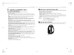
Check the condensate drain system

When all piping and wiring is completed the condensate drain system (including the pump) should be checked for 
correct operation and leaks. If there are any abnormal sounds, leaks, or if the condensate water does not flow 
normally, the problem should be diagnosed and corrected before the system is certified for operation.
In the test run, check that water drain is properly performed and water does not leak from the connecting part of 
the pipes. When doing this, also check that no abnormal sounds are heard from the drain pump motor. Check 
draining also when installed in heating period.

When the electrical and wiring work has been completed

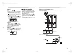
• Pour some water by following the method shown in the following figure. Then, while performing a cooling 

operation, check that the water drains from the drain pipe connecting port (transparent) and that no water is 
leaking from the drain pipe.

When the electrical and wiring work has not been completed

• Disconnect the float switch connector (3P: Green) from the connector (CN80: Green) on the printed circuit board 

inside the electrical control box. (Before doing this, the power must be turned off.)

• Connect a 208 / 230 V supply voltage to (L1) and (L2) on the power supply terminal block. (Do not apply a 208 

/ 230 V voltage to (A), (B) of the terminal block. Otherwise, the printed circuit board may be damaged.)

• Pour the water by following the method shown in the following figure. (Amount of water poured: 0.4 to 0.5 gal 

(1500 to 2000 cc))

• When the power is turned on, the drain pump automatically starts running. Check whether the water is draining 

from the drain pipe connecting port, and check that no water is leaking from the drain pipe.

• After checking that the water drains and there are no water leaks, turn off the power, connect the float switch 

connector to its original location (CN80) on the printed circuit board, and return the electrical control box to its 
original position.

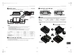
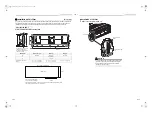
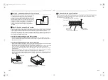
When gravity drainage cannot be provided directly from the indoor 
unit condensate exit the piping can be arranged for upward 
condensate discharge. The vertical leg of the drain line must be a 
maximum of 12” or less from the indoor condensate exit and the 
total vertical height of the leg must be a maximum of 21” or less 
before the drain enters a gravity flow line. These dimensions are 
specified by the indoor unit condensate pump limitations. As 
specified for the gravity flow installation all materials and 
suspension methods must comply with applicable codes and 
regulations.

12” (300 mm) or 

less

Indoor unit

D

o

 no

ra

is

e t

he ho

se

 to


21

” 

(5

50

 mm) o

r l

e

ss

.

208 / 230-1-60

Pull out connector CN80 

(Green) from P.C. board.

White

Red

Black

Black

Insert the end of hose up to the 

near of suction port of drain pump.

Service panel

Condensate drain pipe insulation

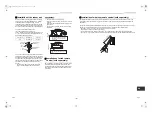
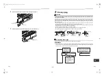
The condensate drain system piping must be insulated to prevent sweating after the leak check is performed. All 
material used in the condensate drain system must comply with applicable codes and regulations covering 
materials installed in the ceiling plenum area.

To cover the pipe and the indoor unit with a heat 

insulator, do not make a space between them.

Pipe insulator

(locally procured)

Fix the insulator with adhesive tape

Pipe insulator

(indoor unit side)

1” drain pipe

(locally procured)

21-EN

22-EN

+00EB99810201_01EN.book  Page 11  Wednesday, June 1, 2016  2:52 PM

Содержание RAV-SP181BT-UL

Страница 1: ...For commercial use Pour usage commercial Indoor Unit Model name Concealed Duct Type RAV SP181BT UL RAV SP241BT UL RAV SP301BT UL RAV SP361BT UL RAV SP421BT UL AIR CONDITIONER SPLIT TYPE Installation Manual 00EB99810201_01EN book Page 1 Wednesday June 1 2016 2 52 PM ...

Страница 2: ... different from the one specified for complement or replacement Otherwise abnormally high pressure may be generated in the refrigeration cycle which may result in a failure or explosion of the product or an injury to your body Connect ground wire grounding work Incomplete grounding may cause an electric shock Do not connect ground wires to gas pipes water pipes lightning rods or ground wires for t...

Страница 3: ...e sure that water dust former refrigerant or refrigerating oil does not enter the refrigerating cycle To prevent charging an incorrect refrigerant and refrigerating oil the sizes of connecting sections of charging port of the main unit and installation tools are changed from those for the conventional refrigerant Accordingly the exclusive tools are required for the new refrigerant R410A For connec...

Страница 4: ...encies are generated by inverter equipment in house power generators medical equipment or communication equipment Malfunctioning or control trouble in the air conditioner or noise may adversely affect the equipment s operation Locations where there is anything under the unit installed that would be compromised by wetness If the drain has become blocked or when the humidity is over 80 condensation ...

Страница 5: ...opening size C 29 5 750 41 3 1050 55 1 1400 Space required for attaching or detaching the filter D 28 7 730 23 6 600 40 5 1030 Electrical control box Air filter locally procured 5 9 150 Ceiling opening size 15 5 400 Min 1 Air discharge Ceiling opening size C Electrical control box Check port A 17 7 17 7 450 450 Air discharge 5 9 150 or more Air intake 1 2 30 Ceiling Ceiling Unit width 31 5 800 Cei...

Страница 6: ...dle it with plastic band at positions other than specified To install vibration isolation material to hanging bolts confirm that it does not increase the unit vibration External dimensions Unit in mm CORRECT INCORRECT INCORRECT 1 room Hanging bolt 4 M0 4 10 locally procured Hanging bolt pitch B Unit external dimension A Air discharge flange outside C 5 5 140 1 7 44 1 9 49 Outside 8 6 218 2 5 8 147...

Страница 7: ...allation of the wired remote control refer to the instructions that are supplied with the control The connection point for the control wiring and the entrance point for the control wiring are clearly marked in the instructions Hanging bolt W3 8 M10 4 pieces Nut W3 8 M10 12 pieces Nut W3 8 M10 M10 flat washer Accessory M10 flat washer Accessory Hanging bolt W3 8 M10 Nut W3 8 M10 Set the air intake ...

Страница 8: ...High 0 15 in WG Standard Air Flow 706 cfm 241 type Mid Low 650 700 750 800 850 900 95010001050110011501200 0 45 0 50 0 30 0 35 0 40 0 45 0 15 0 20 0 25 0 30 0 00 0 05 0 10 0 15 Air flow cfm External Static Pressure in WG High 0 46 in WG High 0 35 in WG High 0 25 in WG High 0 15 in WG Mid Low Standard Air Flow 953 cfm 301 type 0 45 0 50 0 30 0 35 0 40 0 15 0 20 0 25 0 00 0 05 0 10 850 900 950100010...

Страница 9: ...0 15 in WG Standard Air Flow 706 cfm 241 type Mid Low 0 00 0 05 0 10 0 15 0 20 0 25 0 30 0 35 0 40 0 45 0 50 650 700 750 800 850 900 95010001050110011501200 Air flow cfm External Static Pressure in WG High 0 46 in WG High 0 35 in WG High 0 25 in WG High 0 15 in WG Mid Low Standard Air Flow 953 cfm 301 type 0 00 0 05 0 10 0 15 0 20 0 25 0 30 0 35 0 40 0 45 0 50 850 900 95010001050110011501200125013...

Страница 10: ...iece 12 18 1 1 piece 12 25 1 1 piece D H 12 6 320 Remove this cover to install filters in the filter rack Replace the cover after the filters are installed Filter rack W All unit models have the FR 1 FR 2 filter position option available Both positions use the same filters per model shown in the chart above Two positions for filter rack FR 1 FR 2 Indoor unit FR 1 Back air intake flange FR 2 Under ...

Страница 11: ...as shown in the following figure Do not provide any air vents Otherwise the drain water will spout causing water to leak Do not allow any force to be applied to the connection area with the drain pipe Connecting drain pipe Insert the drain socket into the connector until the socket can go no farther REQUIREMENT Connect the hard vinyl chloride pipes certainly so that water does not leak by using ad...

Страница 12: ...s running Check whether the water is draining from the drain pipe connecting port and check that no water is leaking from the drain pipe After checking that the water drains and there are no water leaks turn off the power connect the float switch connector to its original location CN80 on the printed circuit board and return the electrical control box to its original position When gravity drainage...

Страница 13: ...0A is higher than that of R22 Approx 1 6 times Therefore using a torque wrench tighten the flare pipe connecting sections which connect the indoor and outdoor units of the specified tightening torque Incorrect connections may cause not only a gas leak but also a trouble of the refrigeration cycle Align the centers of the connecting pipes and tighten the flare nut as far as possible with your finge...

Страница 14: ...se the power cord and control wire of specified thickness type and protective devices required Do not connect 208 230 V power to the terminal blocks U3 U4 A B etc for control wiring Otherwise the system will fail Perform the electric wiring so that it does not come to contact with the high temperature part of the pipe The coating may melt resulting in an accident Do not turn on the circuit breaker...

Страница 15: ... Secure the ground wire with the ground screw 4 Fix the wires with a cord clamp Unit in mm CAUTION Firmly tighten the screws of the terminal block Keep the wire length as shown in figure below when it is connected to the terminal block Control wire hole Electrical control box cover Screw Screw Conduit connection hole 3 B S A 4 L L Ground screw Cord clamp Conduit pipe System interconnection wires a...

Страница 16: ...erefore install the wired remote control to change the settings Power on SETTING flashes SETTING goes out Remote control is available Approx 5 minutes Power on SETTING flashes SETTING goes out Remote control is available Approx 1 minutes 1 6 1 3 2 5 4 Display content varies with the indoor unit model 2 Each time button is pushed indoor unit numbers in the control group change cyclically Select the...

Страница 17: ...re 4 select the SET DATA of filter sign term from the following table To secure better effect of heating When it is difficult to obtain satisfactory heating due to installation place of the indoor unit or structure of the room the detection temperature of heating can be raised Also use a circulator or other machinery to circulate heat air near the ceiling Follow to the basic operation procedure 1 ...

Страница 18: ...cumulative operating hours x1 h F8 Indoor unit discharge air temperature 1 3 4 2 Group control Group control is not available with the supplied wireless remote control Use the optional wired remote control In case of group control for system of multiple units One remote control can control maximum 8 indoor units as a group In case of group control in single system For wiring procedure and wiring m...

Страница 19: ...played Indoor UNIT No before setup change is displayed Procedure 5 1 Using temp setup buttons specify CODE No 14 CODE No 14 Group address 2 Using timer time buttons change the SET DATA from 0001 to 0002 SET DATA Header unit 0001 Follower unit 0002 3 Push button In this time the setup finishes when the display changes from flashing to lighting Procedure 6 If there is other indoor unit to be changed...

Страница 20: ... Central control is not available with the supplied wireless remote control Use the optional wired remote control Wiring for central control The terminal block for central control wiring and is the same as that for optional wired remote control Connect the central control wire to the terminals and on the terminal block in the same way as the optional wired remote control For details refer to the I...

Страница 21: ...9 or less refrigeration systems when used together with the SMMS series the number of refrigeration systems of the SMMS series is included Since all line addresses are set to 1 except for group control by the automatic address setup function after system power on change the line addresses for each refrigeration system using the wired remote control NOTE For changing setting line addresses using th...

Страница 22: ...ter manual system change 9 Test run Before test run Before turning on the power supply carry out the following procedure 1 By using 500 V megger check that resistance of 1 MΩ or more exists between the terminal block L1 to L2 and the grounding If resistance of less than 1 MΩ is detected do not run the unit 2 Check the valve of the outdoor unit being opened fully To protect the compressor at activa...

Страница 23: ...ay disappears operate the air conditioner according to the following Confirmation of trouble history for confirmation Confirmation of trouble history When a trouble occurred on the air conditioner the trouble history can be confirmed with the following procedure The trouble history is stored in memory up to 4 troubles The history can be confirmed from both operating status and stop status Procedur...

Страница 24: ...M Outdoor unit P C board Outdoor Outdoor P C board In the case of EEPROM trouble Entire stop H01 Outdoor unit compressor breakdown Outdoor Current detect circuit power voltage Minimum frequency was reached in the current releasing control or short circuit current Idc after direct excitation was detected Wiring trouble of compressor open phase Entire stop H02 Outdoor unit compressor lock Outdoor Co...

Страница 25: ...ing etc was detected in the outdoor unit fan drive circuit Entire stop P26 ALT Outdoor unit inverter Idc activated Outdoor IGBT outdoor unit P C board inverter wiring compressor Short circuit protection for compressor drive circuit devices G Tr IGBT was activated Entire stop P29 ALT Outdoor unit position trouble Outdoor Outdoor unit P C board high pressure switch Compressor motor position trouble ...

Страница 26: ...EB99810201 00EB99810201_01EN book Page 46 Wednesday June 1 2016 2 52 PM ...

Отзывы: