22
EN
Digital Inverter
14
TROUBLESHOOTING
You can perform fault diagnosis of the outdoor unit with the LEDs on the P.C. board of the outdoor unit in addition to using the
check codes displayed on the wired remote controller of the indoor unit.
Use the LEDs and check codes for various checks. Details of the check codes displayed on the wired remote controller of the
indoor unit are described in the Installation Manual of the indoor unit.
Verifying current abnormal status
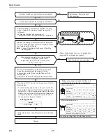
1. Check that DIP switch SW803 is set to OFF.
2. Jot down the states of LED800 to LED804. (Display mode 1)
3. Press SW800 for at least 1 second. The LED status changes to display mode 2.
4. Check the code whose display mode 1 equals the LED states jotted down and display mode 2 equals the current flashing
status of LED800 to LED804 from the following table to identify the cause.
Verifying an abnormal state in the past although the abnormal state no longer occurs
1. Set bit 1 of DIP switch SW803 to ON.
2. Jot down the states of LED800 to LED804. (Display mode 1)
3. Press SW800 for at least 1 second. The LED status changes to display mode 2.
4. Find an error whose display mode 1 equals the LED states jotted down and display mode 2 equals the current flashing
states of LED800 to LED804 from the following table to identify the error.
• An outside
air temperature (TO) sensor error
can be checked only while it occurs.

