background image

Min. volume of the indoor unit installed room (ft³ (m³)) 

≤ Concentration limit (lbs/ft³ (kg/m³))

Check of concentration limit

Warnings on Refrigerant Leakage

The room in which the air conditioner is to be installed requires a design that in the event of refrigerant 

gas leaking out, its concentration will not exceed a set limit.

The refrigerant R410A which is used in the air conditioner is safe, without the toxicity or combustibility of ammonia, 

and is not restricted by laws to be imposed which protect the ozone layer. However, since it contains more than 

air, it poses the risk of suffocation if its concentration should rise excessively. Suffocation from leakage of R410A 

is almost non-existent. With the recent increase in the number of high concentration buildings, however, the 

installation of multi air conditioner systems is on the increase because of the need for effective use of floor space, 

individual control, energy conservation by curtailing heat and carrying power etc.

Most importantly, the multi air conditioner system is able to replenish a large amount of refrigerant compared with 

conventional individual air conditioners. If a single unit of the multi conditioner system is to be installed in a small 

room, select a suitable model and installation procedure so that if the refrigerant accidentally leaks out, its 

concentration does not reach the limit (and in the event of an emergency, measures can be made before injury can 

occur). 

In a room where the concentration may exceed the limit, create an opening with adjacent rooms, or install

mechanical ventilation combined with a gas leak detection device.The concentration is as given below.

The concentration limit of R410A which is used in multi air conditioners is 0.019 lbs/ft³ (0.3 kg/m³)

Total amount of refrigerant (lbs (kg))

If there are 2 or more refrigerating systems in a single refrigerating device, the amounts of refrigerant should be as

charged in each independent device.

2)  When there is an effective opening with the adjacent room for ventilation of leaking refrigerant gas (opening  

  without a door, or an opening 0.15% or larger than the respective floor spaces at the top or bottom of the  

  door).

3)  If an indoor unit is installed in each partitioned room and the refrigerant piping is interconnected, the 

  smallest room of course becomes the object. But when a mechanical ventilation is installed interlocked with  

  a gas leakage detector in the smallest room where the density limit is exceeded, the volume of the next 

  smallest room becomes the object.

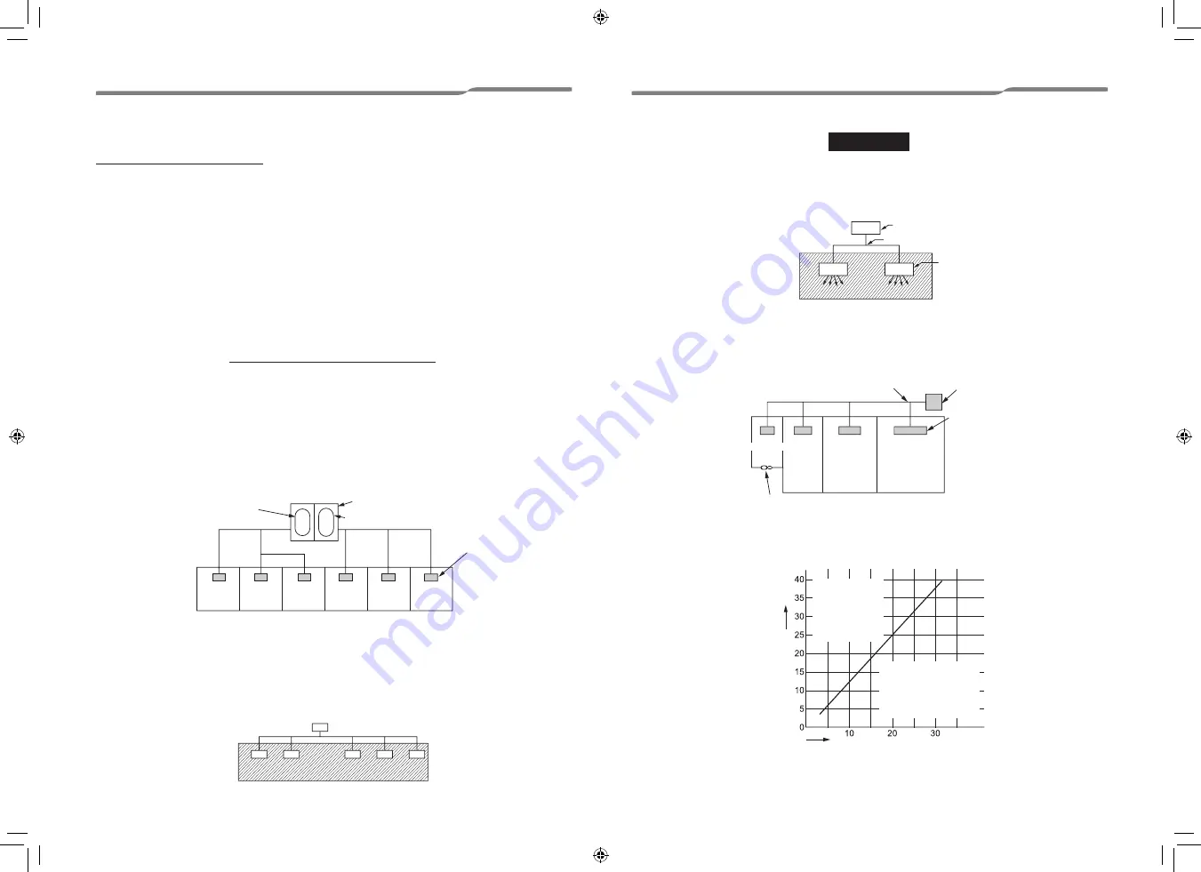
The standards for minimum room volume are as follows.


1)  No partition (shaded portion)

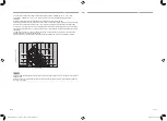
The minimum indoor floor area compared with the amount of refrigerant is roughly as follows:

(When the ceiling is 8ꞌ9" ft (2.7 m) high)

For the amount of charge in this example:

  The possible amount of leaked refrigerant gas in rooms A, B and C is 22 lbs (10 kg.)

  The possible amount of leaked refrigerant gas in rooms D, E and F is 33 lbs (15 kg.)

▼ NOTE 1

▼ NOTE 2

▼ NOTE 3

Outdoor unit

Outdoor unit

Refrigerant piping

Refrigerant piping

Very small room

Total amount of refrigerant

Indoor unit

Outdoor unit

Room A

Room B Room C Room D

Room E Room F

e.g., charged amount 33 lbs (15 kg)

e.g., charged amount 22 lbs (10 kg)

Min. indoor floor area

Mechanical ventilation device - Gas leak detector

Indoor unit

Indoor unit

Large room

Medium 

room

Small 

room

Important

lbs

Range below the 

density limit of 

0.019 lbs/ft³ (0.3 

kg/m³)

(countermeasures 

not needed)

Range above the 

density limit of


0.019 lbs/ft³ (0.3 kg/m³)

(countermeasures 

needed)

57-EN

58-EN

– 29 –

1128950138-00_S01_297x210_96p_S_p70_220212.indd   30

3/23/2022   8:10:52 AM

Содержание RAV-SM122BTP-UL

Страница 1: ...ype RAV SM122BTP UL RAV SM182BTP UL RAV SM242BTP UL RAV SM302BTP UL RAV SM362BTP UL RAV SM422BTP UL RAV SM482BTP UL For commercial use Pour usage commercial Para uso comercial Installation Manual 1 English 1128950138 1128950138 00_S01_297x210_96p_S_p70_220212 indd 1 3 23 2022 8 10 08 AM ...

Страница 2: ...ng to refrigerant handling and piping work on the air conditioners made by Toshiba Carrier Corporation or alternatively he or she has been instructed in such matters by an individual or individuals who have been trained and is thus thoroughly acquainted with the knowledge related to this work The qualified installer who is allowed to work at heights has been trained in matters relating to working ...

Страница 3: ...ry 2 or damage 3 to property if the product is handled improperly 1 Serious bodily harm indicates loss of eyesight injury burns electric shock bone fracture poisoning and other injuries which leave aftereffect and require hospitalization or long term treatment as an outpatient 2 Slight injury indicates injury burns electric shock and other injuries which do not require hospitalization or long term...

Страница 4: ...heights using a stand of 19 7 50 cm or more or to remove the intake grille of the indoor unit to undertake work Wear protective gloves and safety work clothing during installation servicing and removal Do not touch the aluminium fin of the unit You may injure yourself if you do so If the fin must be touched for some reason first put on protective gloves and safety work clothing and then proceed Be...

Страница 5: ...ing the air conditioner If the compressor is operated with the valve open and without refrigerant pipe the compressor sucks air and the refrigeration cycles is over pressurized which may cause an injury Tighten the flare nut with a torque wrench in the specified manner Over tightening tighten of the flare nut may cause a crack in the flare nut after a long period which may result in refrigerant le...

Страница 6: ... circuit breaker outdoors install one which is designed to be used outdoors Electrical wiring 5 Under no circumstances the power wire must not be extended Connection trouble in the places where the wire is extended may give rise to smoking and or a fire Electrical wiring work shall be conducted according to law and regulation in the community and installation manual Failure to do so may result in ...

Страница 7: ...f at least 0 1 3 mm The installation fuse all types can be used must be used for the power supply line of this conditioner CAUTION Explanations given to user Upon completion of the installation work tell the user where the circuit breaker is located If the user does not know where the circuit breaker is he or she will not be able to turn it off in the event that trouble has occurred in the air con...

Страница 8: ...d Blocked filters may cause the air conditioner s performance to deteriorate condensation to form the plastic parts to be damaged and other such problems to result Locations near obstructions such as ventilation openings or lighting fixtures where the flow of the blown air will be disrupted a disruption of the air flow may cause the air conditioner s performance to deteriorate or the unit to shut ...

Страница 9: ...olume Low air volume operation time 4 hours Installation space Unit in mm Reserve sufficient space required for installation or service work Air discharge Ceiling A B 1 0 25 1 0 25 Inspection opening Ceiling opening 3 9 100 or more or more 98 4 2500 or more 2 8 70 or more 10 8 275 Floor surface 0 2 5 or more Ceiling Air intake Inspection opening Ceiling opening 22 4 570 1 0 25 Air discharge 3 9 10...

Страница 10: ...ces Installation of hanging bolt Use M10 hanging bolts 4 pcs locally procured Matching to the existing structure set pitch according to size in the unit external view as shown below New concrete slab Install the bolts with insert brackets or anchor bolts Steel flame structure Use existing angles or install new support angles Existing concrete slab Use a hole in anchors hole in plugs or a hole in b...

Страница 11: ...r 2 Remove Electrical control box cover and Partition electrical cover Remove the screws 1 parts Remove the Electrical control box cover Electrical cover 1 hole Partition electrical cover Remove Remove Grommet Screws 3 Change part electrical cover 1 hole to 2 holes and attach Electrical control box cover Electrical cover 2 holes 4 Attach the Electrical control box cover to unit Attach the screws 4...

Страница 12: ... where the pipe connects to the indoor unit with proper heat insulation Improper heat insulation will cause condensation to form The drain pipe must be sloping downward at an angle of 1 100 or more and do not run the pipe up and down arched shape or allow it to form traps Doing so may cause abnormal sounds Restrict the length of the traversing drain pipe to 65 6 20 m or less For a long pipe provid...

Страница 13: ...llowing the method shown in the following figure Then while performing a cooling operation check that the water drains from the drain pipe connecting port transparent and that no water is leaking from the drain pipe When the electrical and wiring work has not been completed To ensure the power has been turned off Disconnect the float switch connector 3P red from the connector CN34 red on the print...

Страница 14: ...om the surface of the indoor unit Insulation locally procured Insulation of the drain connecting section accessory Indoor unit Duct Insulation material locally procured Connect a duct to the outside of the flange Flange locally procured Aluminum tape locally procured Aluminum tape locally procured Under surface Air intake side Indoor unit Flange Air discharge side CAUTION Incomplete insulation of ...

Страница 15: ...in WG High tap 0 2 in WG High tap 300 500 700 900 1100 1300 1500 1700 1900 RAV SM362BTP UL RAV SM422BTP UL RAV SM482BTP UL Standard air flow 1177 CFM 1 1 1 0 0 9 0 8 0 7 0 6 0 5 0 4 0 3 0 2 0 1 0 0 Air flow rate CFM 300 500 700 900 1100 1300 1500 1700 1900 2100 0 6 in WG Mid tap 0 2 in WG Mid tap 0 6 in WG Low tap 0 2 in WG Low tap Standard filter pressure loss 0 8 in WG High tap 0 6 in WG High ta...

Страница 16: ... star mark is below 0 6 in WG high speed fan tap line which means the unit needs to be set to 0 6 in WG external static pressure with high speed fan tap Please follow the process described in application controls of this manual for set up external static pressure NOTE Supply air CFM will follow the solid line fan curve shown in the above graph if there is any change in the external static pressure...

Страница 17: ...3 6 1359 4 9 3 235 4 10 0 254 1 1 27 3 9 100 3 9 100 1 1 27 1 5 37 5 1 5 37 5 3 9 100 3 9 100 3 9 100 3 9 100 3 9 100 3 9 100 3 9 100 3 9 100 3 9 100 3 9 100 3 9 100 3 9 100 3 9 100 26 0 659 4 9 3 235 2 10 0 254 1 1 27 3 9 100 3 9 100 1 1 27 3 4 87 5 3 4 87 5 3 9 100 3 9 100 3 9 100 3 9 100 3 9 100 26 6 675 37 8 960 9 3 235 2 10 0 254 1 1 27 3 9 100 3 9 100 1 1 27 1 5 37 5 1 5 37 5 3 9 100 3 9 100...

Страница 18: ...double spanner Use the tightening torque levels as listed in the following table Unit ft lbs N m Outer dia of connecting pipe Tightening torque 1 4 6 4 mm 10 13 14 18 3 8 9 5 mm 24 31 33 42 1 2 12 7 mm 37 46 50 62 5 8 15 9 mm 50 60 68 82 Tightening torque of flare pipe connections Pressure of R410A is higher than that of R22 Approx 1 6 times Therefore using a torque wrench tighten the flare pipe c...

Страница 19: ...ock or a fire CAUTION For power supply specifications follow the Installation Manual of outdoor unit Do not connect 208 230V 60 Hz power to the terminal blocks A B for control wiring Otherwise the system will fail Do not damage or scratch the conductive core and inner insulator of power and system interconnection wires duringpeeling them Perform the electric wiring so that it does not come to cont...

Страница 20: ...res through the bushing of wire connection holes of the indoor unit Keep a margin Approx 3 9 100 mm on a wire to hang down the electrical control box at servicing or other purpose The low voltage circuit is provided for the remote controller Do not connect the high voltage circuit Before performing wiring work in the electrical control box remove the air filter and the cover of the box fixed with ...

Страница 21: ...factor 5 Setting louver position Change the louver indication setting to match the indoor unit type 6 Setting timer operation mode Set whether or not the operation mode can be selected when setting the schedule timer 7 DN setting Advanced settings using DN code DN setting Perform the advanced settings for the air conditioner Carry out the setting operation while the indoor unit is stopped Turn off...

Страница 22: ...e indoor unit or structure of the room the detection temperature of heating can be raised Also use a circulator or other device to circulate heat air near the ceiling Follow to the basic operation procedure 1 2 3 4 5 6 For the CODE No in Procedure 3 specify 06 For the SET DATA in Procedure 4 select the SET DATA of shift value of detection temperature to be set up from the following table Energy sa...

Страница 23: ...to select 4 Monitor function on the Field setting menu screen then push the Set F2 button Push the button to select the code to check data 2 Refer to the Installation Manual supplied with the indoor unit or outdoor unit or service manual for details about the check code and data 3 Push the CANCEL button to return to the Field setting menu screen Indoor unit data CODE No Data name 01 Room temperatu...

Страница 24: ... indoor addresses are set randomly For this reason change the setting to match line addresses with indoor addresses NOTE Procedure example 1 Procedure example Manual address setup procedure While the operation stops change the setup Stop the operation of the unit 1 Push the MENU button to display the menu screen Push and hold the MENU button and the button at the same time to display the Field set...

Страница 25: ...ed Indoor UNIT No before setup change is displayed 7 After check of the changed contents Push the No F2 button to finish the setting operation Setting appears on the screen for a while then the screen returns to the Field setting menu screen Pushing the No F2 button displays the unit selection screen when the group control is used Push the CANCEL button on the unit selection screen to finish the s...

Страница 26: ...ion of check code date time and unit 4 Monitor function Monitoring data of sensor temperature rotating speed of the compressor or other factor 5 Setting louver position Change the louver indication setting to match the indoor unit type 6 Setting timer operation mode Set whether or not the operation mode can be selected when setting the schedule timer 7 DN setting Advanced settings using DN code Wi...

Страница 27: ...ar Following inspection must be carried out by a qualified installer or qualified service person Parts Inspection method Heat exchanger Access from inspection opening and remove the access panel Examine the heat exchanger if there is any clogging or damages Fan motor Access from inspection opening and check if any abnormal noise can be heard Fan Access from inspection opening and remove the access...

Страница 28: ...d Auto reset E09 Duplicated header remote controllers Remote controller Remote controller address setting error Two remote controllers are set as header in the double remote controller control The header indoor unit stops raising alarm and follower indoor units continue to operate E10 CPU CPU communication error Indoor Indoor P C board Communication error between main MCU and motor microcomputer M...

Страница 29: ...N80 Entire stop L31 SIM Phase sequence error etc Outdoor Power supply phase sequence outdoor unit P C board Abnormal phase sequence of the 3 phase power supply Operation continued thermost at OFF Wired remote controller display Wireless remote controller Sensor block display of receiving unit Main defective parts Judging device Parts to be checked error description Air conditioner status Indicatio...

Страница 30: ...in multi air conditioners is 0 019 lbs ft 0 3 kg m Total amount of refrigerant lbs kg If there are 2 or more refrigerating systems in a single refrigerating device the amounts of refrigerant should be as charged in each independent device 2 When there is an effective opening with the adjacent room for ventilation of leaking refrigerant gas opening without a door or an opening 0 15 or larger than t...

Страница 31: ...TANDARD 0000 STATIC 1 0001 STATIC 2 0002 STATIC 3 0003 STATIC 4 0004 STATIC 5 0005 STATIC 6 0006 Have you changed lighting time of filter sign If not fill check mark in NO CHANGE and fill check mark in ITEM if changed respectively For check method refer to APPLICABLE CONTROLS in this manual Filter sign lighting time CODE NO 01 NO CHANGE NONE 0000 150H 0001 2500H 0002 5000H 0003 10000H 0004 Filter ...

Страница 32: ...144 9 Moo 5 Bangkadi Industrial Park Tivanon Road Tambol Bangkadi Amphur Muang Pathumthani 12000 Thailand 1128950138 1128950138 00_S01_297x210_96p_S_p70_220212 indd 96 3 23 2022 8 12 28 AM ...

Отзывы: