background image

Toshiba XXXXXXX(

X

/X)

Toshiba XXXXXXX(

X

/X)

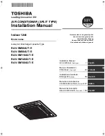
AIR CONDITIONER (SPLIT TYPE)

Indoor Unit

Model name:

4-way Air Discharge Cassette Type

RAV-SM564UT-E
RAV-SM804UT-E
RAV-SM1104UT-E
RAV-SM1404UT-E
RAV-SM1604UT-E

Not accessible to the general public

Vente interdite au grand public

Kein öffentlicher Zugang

Non accessibile a clienti generici

No destinado al público en general

Installation Manual

Installation Manual

Air conditioner 

(Split type)

1

English

Manuel d’installation

Climatiseur 

(Type split)

43

Français

Installations-handbuch

Klimagerät 

(Split-typ)

85

Deutsch

Manuale di installazione

Condizionatore d’aria 

(Tipo split)

127

Italiano

Manual de instalación

Aire acondicionado 

(Tipo split)

169

Español

+00EH99858901-1_01EN_4-way_IM.book  Page 1  Tuesday, June 3, 2008  6:30 PM

Содержание RAV-SM1104UT-E

Страница 1: ...blic Kein öffentlicher Zugang Non accessibile a clienti generici No destinado al público en general Installation Manual Installation Manual Air conditioner Split type 1 English Manuel d installation Climatiseur Type split 43 Français Installations handbuch Klimagerät Split typ 85 Deutsch Manuale di installazione Condizionatore d aria Tipo split 127 Italiano Manual de instalación Aire acondicionado...

Страница 2: ...0 MAINTENANCE 35 11 TROUBLE SHOOTING 38 Please read this Installation Manual carefully before installing the Air Conditioner This Manual describes the installation method of the indoor unit For installation of the outdoor unit follow the Installation Manual attached to the outdoor unit ADOPTION OF NEW REFRIGERANT This Air Conditioner is a new type which adopts a new refrigerant HFC R410A instead o...

Страница 3: ...r and adjust corner caps with a receiver section Part name Q ty Shape Usage Installation Manual 2 These manual Be sure to hand over to customers Heat insulating pipe 2 For heat insulation of pipe connecting section Installation pattern 1 For confirmation of ceiling opening and indoor unit position Installation gauge For positioning of ceiling position Washer 4 For hanging down unit Eccentric washe...

Страница 4: ... in the refrigeration cycle becomes abnormally high and it resultingly causes pipe burst and injuries on persons Perform installation work properly according to the Installation Manual Inappropriate installation may result in water leakage electric shock or fire When the air conditioner is installed in a small room provide appropriate measures to ensure that the concentration of refrigerant leakag...

Страница 5: ... sizes of connecting sections of charging port of the main unit and installation tools are changed from those for the conventional refrigerant Accordingly the exclusive tools are required for the new refrigerant R410A For connecting pipes use new and clean piping designed for R410A and please care so that water or dust does not enter To Disconnect the Appliance from Main Power Supply This applianc...

Страница 6: ...t exchanger and resin part turbo fan in the indoor unit may reduce the performance generate mist or dew drop or deform or damage resin parts Place where organic solvent is used nearby Place close to a machine generating high frequency Place where the discharged air blows directly into the window of the neighbor house Outdoor unit Place where noise of the outdoor unit is easily transmitted When ins...

Страница 7: ...material glass wool etc additionally on all the positions of the indoor unit which come to contact with high humidity atmosphere REQUIREMENT When the humidity inside the ceiling seems to be higher than 80 attach a heat insulator to the side top surface of the indoor unit Use a heat insulator that is 10mm or more thick Ceiling height When the height of the ceiling exceeds the distance of the item S...

Страница 8: ...eating due to location place of the indoor unit or the structure of the room the detection temperature of heating can be raised Discharge direction As shown in the figure below air discharge directions can be selected according to the shape of the room and the location of the indoor unit installation Use a shielding plate kit sold separately to change discharge directions Discharge directions are ...

Страница 9: ...56 Type 256 Ø6 4 Ø12 7 120 SM140 Type 319 Ø9 5 Ø15 9 183 SM80 Type 256 Ø9 5 Ø15 9 120 SM160 Type 319 Ø9 5 Ø15 9 183 SM110 Type 319 Ø9 5 Ø15 9 183 Ceiling bottom surface Ceiling bottom surface 840 Unit external dimension 950 Ceiling opening dimension 860 to 910 Panel external dimension 690 20 Hanging bolt pitch Z view 860 to 910 Ceiling opening dimension 950 Panel external dimension 780 Hanging bol...

Страница 10: ...four holes in the installation pattern to the panel fixing screws of the indoor unit When hanging a ceiling open the ceiling along the outside dimensions of the installation pattern Treatment of ceiling The ceiling differs according to structure of building For details consult your constructor or interior finish contractor In the process after the ceiling board has been removed it is important to ...

Страница 11: ... the installation gauge is printed on the gauge REQUIREMENT Before installation of the indoor unit be sure to remove the cushion for transportation between the fan and the bell mouth Running the unit without removing the cushion may damage the fan motor Hanging bolt Level Hanging bracket Washer Accessory To prevent the bolt from falling off for safety be sure to set it just under the hanging brack...

Страница 12: ...ired remote controller follow the Installation Manual attached with the remote controller Pull out the remote controller cord together with the refrigerant pipe or drain pipe Be sure to pass the remote controller cord through upper side of the refrigerant pipe and drain pipe Do not leave the remote controller at a place exposed to the direct sunlight and near a stove In case of wireless type The s...

Страница 13: ...al of 1 5 to 2m in order to prevent waving Set the collective piping as shown in the below figure Be sure not to apply force to the connecting part of the drain pipe The hard vinyl chloride pipe cannot be directly connected to the drain pipe connecting port of the indoor unit For connection with the drain pipe connecting port be sure to use fix the attached flexible hose with the hose band otherwi...

Страница 14: ...ater does not leak from the connecting part of the pipes Be sure to check draining also when installed in heating period Using a pitcher or hose pour water 1500 to 2000cc into the discharge port before installation of the ceiling panel Pour water gradually so that water does not spread on the motor of the drain pump CAUTION Pour water gently so that it does not spread around inside the indoor unit...

Страница 15: ...bottom of the indoor unit without gap Cover the drain pipe seamlessly with a heat insulator to be procured locally so that it overlaps with the attached heat insulator of the drain connecting section Direct the slits and seams of the heat insulator upward to avoid water leakage 1 2 Pull out connector CN34 Red from P C board CN34 RED Black Black Red White Single phase 220 240V Power terminals Wrap ...

Страница 16: ...ipes using VACUUM PUMP 4 Check the gas leakage Connected points Pipe size Permissible Piping Length and Height Difference They vary according to the outdoor unit For details refer to the Installation Manual attached to the outdoor unit Flaring Cut the pipe with a pipe cutter Remove burrs completely Remaining burrs may cause gas leakage Insert a flare nut into the pipe and flare the pipe As the fla...

Страница 17: ...as charge hose etc use those manufactured exclusively for R410A Refrigerant amount to be added For addition of the refrigerant add refrigerant R410A referring to the attached Installation Manual of outdoor unit Be sure to use a scale to charge the refrigerant of specified amount REQUIREMENT Charging an excessive or too little amount of refrigerant causes a trouble of the compressor Be sure to char...

Страница 18: ... Using the attached thermal insulation material apply the thermal insulation to the pipe connecting section of the indoor unit securely without gap REQUIREMENT Apply the thermal insulation to the pipe connecting section of the indoor unit securely up to the root without exposure of the pipe The pipe exposed to the outside causes water leak Wrap heat insulator with its slits facing up ceiling side ...

Страница 19: ...ness type and protective devices required REQUIREMENT For power supply wiring strictly conform to the Local Regulation in each country For wiring of power supply of the outdoor units follow the Installation Manual of each outdoor unit Never connect 220 240V power to the terminal blocks etc for control wiring Otherwise the system will fail Perform the electric wiring so that it does not come to con...

Страница 20: ... fix the wires with cord clamp attached to the electric parts box Do not apply tension to the connecting section of the terminal block Using the attached thermal insulation material seal the pipe connecting port Otherwise dewing may be caused Mount the cover of the electric parts box without pinching wires Mount the cover after wiring on the ceiling panel 1 2 3 A B Hinge Screws a 2 positions Louve...

Страница 21: ...iring of the remote controller 0 5mm to 2 0mm wires For the synchronous twin triple system use 2 core shield wire MVVS 0 5 to 2 0 mm to conform to the EMC standard Wiring diagram For details of wiring installation of the remote controller refer to the Installation Manual enclosed to in the remote controller Single system Synchronous twin system Make a loop on the wire for margin of the length so t...

Страница 22: ...ld wire to the earth Connect earth wire for each indoor unit in the synchronous twin and synchronous triple systems A B 1 2 3 A B 1 1 L N 2 2 3 3 Indoor side Indoor Outdoor connecting wires Remote controller Remote controller wiring Outdoor side Remote controller inter unit wiring Indoor power inter unit wiring Indoor side 220 240V A B 1 2 3 A B 1 1 L N 2 2 3 3 A B 1 2 3 Indoor side Indoor Outdoor...

Страница 23: ...on and temp setup button simultaneously for at least 4 seconds After a while the display flashes as shown in the figure Confirm that the CODE No is 01 If the CODE No is not 01 push button to erase the display content and repeat the procedure from the beginning No operation of the remote controller is accepted for a while after button is pushed Procedure 2 Each time you push button indoor unit numb...

Страница 24: ...ing When an indoor unit is installed on a ceiling higher than the standard height make the high ceiling setting for air volume adjustment Take the same procedure as that in When installing separately sold filters Select the setting data for Procedure 4 from the Height list of ceiling possible to be installed table on page 7 in this manual When wireless remote controller is used Change the high cei...

Страница 25: ...tton Indoor unit number changes each time you push the button The fan of the selected unit runs and the louvers start swinging 3 Change the CODE No to 45 with TEMP buttons 4 Select wind direction setting with TIME buttons 5 Push button to check the setting The display state changes from flashing to lighting and the setting is fixed 6 Push button to end the setting When the cold draft position is s...

Страница 26: ...itioner is not working flashes Indicates CODE No F1 2 Select an indoor unit to be set by pushing left side of the button Each time you push the button unit numbers change as follows The fan of the selected unit runs and the louvers start swinging 3 Select a louver you want to lock by pushing TEMP buttons 4 Select the wind direction of the louver you do not want to swing by pushing TIME buttons Whe...

Страница 27: ...and outdoor unit 1 Push and buttons simultaneously for at least 4 seconds to call the service monitor mode The service monitor indicator lights up and the header indoor unit number is displayed first CODE No is also displayed 2 Pushing TEMP buttons select the number of sensor etc CODE No to be monitored See the following table 3 Pushing left side of the button select an indoor unit to be monitored...

Страница 28: ... of the indoor unit connected with a remote controller to the terminal blocks A B of the indoor units of other indoor units by wiring the inter unit wire of the remote controller When the power supply has been turned on the automatic address setup starts and which indicates that address is being set up flashes on the display part During setup of automatic address the remote controller operation is...

Страница 29: ... Line system Indoor No After setup of automatic address Example of random setup After setup change of manual address Example of address setup change Outdoor unit Indoor unit Indoor unit Indoor unit Line address Group address Indoor address Address 1 1 1 Address 2 1 2 Address 2 2 2 Address 1 1 2 Address 2 1 2 Address 3 3 1 Procedure example Single system Twin system Triple system Outdoor unit Indoo...

Страница 30: ...ouver of the selected indoor unit operate Procedure 3 1 Using temp setup buttons specify CODE No 12 CODE No 12 Line address 2 Using timer time buttons change the line address from 3 to 2 3 Push button In this time the setup finishes when the display changes from flashing to lighting Procedure 4 1 Using temp setup buttons specify CODE No 13 CODE No 13 Indoor address 2 Using timer time buttons chang...

Страница 31: ...ition during operation stop Be sure to stop operation of the set Procedure 1 Push simultaneously buttons for 4 seconds or more After a while the display part flashes and the display appears as shown below In this time the position can be checked because fan and louver of the indoor unit operate For the group control the indoor unit No is displayed as and fans and louvers of all the indoor units in...

Страница 32: ...order Select the indoor unit of which setup is changed In this time the position of the indoor unit of which setup is changed can be confirmed because fan and louver of the selected indoor unit operate Procedure 3 Using temp setup buttons specify CODE No d1 Procedure 4 Using timer time buttons select SET DATA 0001 Procedure 5 Push button In this time the setup finishes when the display changes fro...

Страница 33: ... order to prevent a serial operation the forced test run is released after 60 minutes have passed and returns to the usual operation CAUTION Do not use the forced test run for cases other than the test run because it applies an excessive load to the devices In case of wired remote controller Procedure 1 Keep button pushed for 4 seconds or more TEST is displayed on the display part and the selectio...

Страница 34: ... repeat procedures 2 to 5 Procedure 7 Upon completion of the test run push ON OFF button to stop operation Overview of test run operations using the wireless remote controller Cooling test run ON OFF 18 C 19 C 18 C 19 C 18 C 19 C 18 C test run ON OFF Heating test run ON OFF 30 C 29 C 30 C 29 C 30 C 29 C 30 C test run ON OFF Cooling test run Heating test run Set the temperature to 18 C with the tem...

Страница 35: ...at least 4 seconds 2 flashes on the display as shown in the following figure 3 Push button changes from flashing to lighting 4 Push button disappears and SETTING flashes It takes 5 minutes 5 When SETTING disappears re setting is completed and the air conditioner enter the normal operation standby mode A 1 2 3 B 1 2 3 A 1 2 3 B A 1 2 3 B 1 2 3 A 1 2 3 B Incorrect connection Indoor unit Outdoor unit...

Страница 36: ...failure in the air conditioner such as water falling in drops Preparation 1 Stop the operation by remote controller 2 Dismount the air filter Use a vacuum cleaner to remove dust from the filters or wash them with water After rinsing the air filters with water dry them in the shade Set the air filter into the air conditioner Clean the panel and air filter with water Wipe down the panel and air filt...

Страница 37: ...y to ensure efficient operation of the air conditioner When the air conditioner is operated for a long time periodic maintenance once a year is recommended Furthermore regularly check the outdoor unit for rust and scratches and remove them or apply rustproof treatment if necessary As a general rule when an indoor unit is operated for 8 hours or more daily clean the indoor unit and outdoor unit at ...

Страница 38: ...en it is damaged Fan Indoor Vibration balance Dust dirt appearance Replace the fan when vibration or balance is terrible Brush or wash the fan when it is contaminated Air inlet outlet grilles Indoor outdoor Dust dirt scratches Fix or replace them when they are deformed or damaged Drain pan Indoor Dust dirt clogging drain contamination Clean the drain pan and check the downward slope for smooth dra...

Страница 39: ...tory can be confirmed from both operating status and stop status Procedure 1 When pushing and buttons at the same time for 4 seconds or more the following display appears If Service check is displayed the mode enters in the trouble history mode 01 Order of trouble history is displayed in CODE No window Check code is displayed in CHECK window Indoor unit address in which an error occurred is displa...

Страница 40: ...lower unit regular communication error Indoor Indoor P C board Regular communication is not possible between header and follower indoor units or between twin header main and follower sub units Auto reset E31 IPDU communication error Outdoor Communication error between IPDU and CDB Entire stop F01 ALT Indoor unit heat exchanger sensor TCJ error Indoor Heat exchanger sensor TCJ indoor P C board Open...

Страница 41: ...tdoor unit error Entire stop 1 Communication error between IPDU MCU and CDB MCU Entire stop 2 Abnormal temperature was detected by the heat sink temp sensor in IGBT L30 SIM Abnormal external input into indoor unit interlock Indoor External devices outdoor unit P C board Abnormal stop due to incorrect external input into CN80 Entire stop L31 SIM Phase sequence error etc Outdoor Power supply phase s...

Страница 42: ...ization Receiving unit display OR Orange GR Green P26 ALT Outdoor unit inverter Idc activated Outdoor IGBT outdoor unit P C board inverter wiring compressor Short circuit protection for compressor drive circuit devices G Tr IGBT was activated Entire stop P29 ALT Outdoor unit position error Outdoor Outdoor unit P C board high pressure switch Compressor motor position error was detected Entire stop ...

Страница 43: ... 42 4 way Air Discharge Cassette Type Installation Manual EN 42 EN ...

Страница 44: ...EH99858901 A ...

Отзывы: