background image

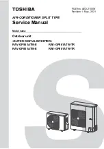
Model name:

AIR-CONDITIONER SPLIT TYPE

Outdoor unit

<SUPER DIGITAL INVERTER>
RAV-GP561ATW-E
RAV-GP801ATW-E

RAV-GP561ATW-TR
RAV-GP801ATW-TR

Service Manual

FILE No. AEO-2103W

Revision 1: May, 2021

Содержание RAV-GP561ATW-E

Страница 1: ...Model name AIR CONDITIONER SPLIT TYPE Outdoor unit SUPER DIGITAL INVERTER RAV GP561ATW E RAV GP801ATW E RAV GP561ATW TR RAV GP801ATW TR Service Manual FILE No AEO 2103W Revision 1 May 2021 ...

Страница 2: ...GERANTING CYCLE DIAGRAM 35 4 WIRING DIAGRAM 38 4 1 RAV GP561ATW 38 4 2 RAV GP801ATW 39 5 SPECIFICATIONS OF ELECTRICAL PARTS 40 5 1 Outdoor Unit 40 5 2 Winding resistance of outdoor unit main parts 41 6 REFRIGERANT R32 42 6 1 Safety During Installation Servicing 42 6 2 Refrigerant Piping Installation 42 6 2 1 Piping Materials and Joints Used 42 6 2 2 Processing of Piping Materials 43 6 3 Tools 46 6...

Страница 3: ... 2 Others Other than Check Code 65 8 2 3 Monitor Function of Remote Controller Switch 66 8 2 4 Check Code List Outdoor 67 8 2 5 Diagnostic Procedure for Each Check Code Outdoor Unit 73 9 SETUP AT LOCAL SITE AND OTHERS 84 9 1 Calling of Check code History 84 9 2 Outdoor Unit 86 10 ADDRESS SETUP 95 10 1 Address Setup Procedure 95 10 2 Address Setup Group Control 96 10 2 1 System Configuration 97 10 ...

Страница 4: ... individuals who have been trained and is thus thoroughly acquainted with the knowledge related to this work The qualified installer who is allowed to work at heights has been trained in matters relating to working at heights with the air conditioners made by Toshiba Carrier Air conditioning Europe Sp z o o or alterna tively he or she has been instructed in such matters by an individual or individ...

Страница 5: ...electric shock Work done at heights 50 cm or more Helmets for use in industry Transportation of heavy objects Shoes with additional protective toecap Repair of outdoor unit Gloves to provide protection for electricians Indication Explanation DANGER Indicates contents assumed that an imminent danger causing a death or serious injury of the repair engineers and the third parties when an incorrect wo...

Страница 6: ...ore operation Service personnel are required to carefully read the OWNER S MANUAL and INSTALLATION MANUAL before operation Further information is available in the OWNER S MANUAL INSTALLATION MANUAL and the like Warning indication Description WARNING ELECTRICAL SHOCK HAZARD Disconnect all remote electric power supplies before servicing WARNING Moving parts Do not operate unit with grille removed St...

Страница 7: ... CAUTION BURST HAZARD Open the service valves before the operation otherwise there might be the burst CAUTION Do not touch the aluminum fins of the unit Doing so may result in injury CAUTION Do not touch the aluminum fins of the unit You might get burned CAUTION BURST HAZARD Open the service valves before the operation otherwise there might be the burst ...

Страница 8: ...the interior parts Only a qualified installer 1 or qualified service person 1 is allowed to remove the intake grille of the indoor unit or service panel of the outdoor unit and do the work required Before starting to repair the outdoor unit fan or fan guard be absolutely sure to set the circuit breaker to the OFF position and place a Work in progress sign on the circuit breaker When cleaning the f...

Страница 9: ...arts and other objects may fall from above possibly injuring a person below Do not touch the aluminum fin of the outdoor unit You may injure yourself if you do so If the fin must be touched for some reason first put on protective gloves and safety work clothing and then proceed Do not climb onto or place objects on top of the outdoor unit You may fall or the objects may fall of the outdoor unit an...

Страница 10: ...vice Manual Use of any parts which do not satisfy the required specifications may give rise to electric shocks smoking and or a fire Replace components only with parts specified by the manufacturer Other parts may result in the ignition of refrigerant in the atmosphere due to the refrigerant leak Do not bring a child close to the equipment If in the course of carrying out repairs it becomes absolu...

Страница 11: ... over the specified amount When recharging the refrigerant in the refrigerating cycle do not mix the refrigerant or air other than R32 into the specified refrigerant If air or others is mixed with the refrigerant abnormal high pressure generates in the refrigerating cycle resulted in cause of injury due to breakage After the installation work confirm that refrigerant gas does not leak If refrigera...

Страница 12: ...lowing matters before a test run after repairing piping Connect the pipes surely and there is no leak of refrigerant The valve is opened Running the compressor under condition that the valve closes causes an abnormal high pressure resulted in damage of the parts of the compressor and etc and moreover if there is leak of refrigerant at connecting section of pipes the air is suctioned and causes fur...

Страница 13: ...ble gas leaks and becomes concentrated around the unit a fire may occur When transporting the air conditioner use a forklift truck and when moving the air conditioner by hand move the unit with 4 people Install a circuit breaker that meets the specifications in the Installation Manual and the stipulations in the local regulations and laws Install the circuit breaker where it can be easily accessed...

Страница 14: ...ioner Model type RAV GP561ATW E RAV GP801ATW E RAV GP561ATW TR RAV GP801ATW TR Commercial name Super Digital Inverter Series Air Conditioner Complies with the provisions of the Machinery Directive Directive 2006 42 EC and the regulations transposing into national law Complies with the provisions of the following harmonized standard EN 378 2 2016 Name Morizono Takahiro Position GM Quality Assurance...

Страница 15: ...ure to check for leakage refrigerant or residual refrigerant If the leakage refrigerant comes into contact with fire a poisonous gas may occur or it may cause a fire Keep adequate ventilation during the work 4 When refrigerant gas leaks during work execute ventilation If the leakage refrigerant comes into contact with a fire a poisonous gas may occur or it may cause a fire 5 In places where instal...

Страница 16: ...s charge it with liquid 3 Pipe Materials For the refrigerant pipes copper pipe and joints are mainly used It is necessary to select the most appropriate pipes to conform to the standard Use clean pipes or joints to which little impurities adhere 1 Copper pipe Be sure to select the pipes with copper thickness in the table below since the pressure of an air conditioner using R32 is higher than that ...

Страница 17: ...g work Miss charging of the refrigerant type may cause not only damage of the equipment but also a fire etc General tools No Installation service tools Use Applicability to R32 air conditioner or not Applicability to R22 air conditioner or not Tools Equipment specification 1 Flare tool Clutch type Pipe flaring 2 Copper pipe gauge for adjusting projection margin Flaring by conventional flare tool 3...

Страница 18: ...10 A A Maximum current A 13 1 20 3 Indoor unit Fan unit Fan Turbo fan Turbo fan Standard air flow H M M L L m min 17 5 16 5 15 0 13 5 12 5 32 0 23 2 21 5 19 0 13 5 Motor W 60 130 Sound pressure level H M M L L dB A 32 31 29 28 26 42 37 35 32 27 Sound power level H M M L L dB A 48 47 45 44 43 56 50 49 46 43 Outdoor unit Length of refrigerant pipe Max total length m 50 50 Min length m 3 3 Height dif...

Страница 19: ... Lot10 A A Maximum current A 13 1 20 3 Indoor unit Fan unit Fan Turbo fan Turbo fan Standard air flow H M M L L m min 17 5 14 5 13 0 20 5 16 0 13 5 Motor W 14 20 Sound pressure level H M M L L dB A 32 29 28 35 31 28 Sound power level H M M L L dB A 47 44 43 50 46 43 Outdoor unit Length of refrigerant pipe Max total length m 50 50 Min length m 3 3 Height difference Outdoor lower m 30 30 Outdoor hig...

Страница 20: ...iency class Lot10 A Maximum current A 13 1 Indoor unit Fan unit Fan Turbo fan Standard air flow H M M L L m min 13 3 12 0 11 2 9 4 9 1 Motor W 60 Sound pressure level H M M L L dB A 44 42 39 36 35 Sound power level H M M L L dB A 59 57 54 51 50 Outdoor unit Length of refrigerant pipe Max total length m 50 Min length m 3 Height difference Outdoor lower m 30 Outdoor high m 30 Fan unit Fan Propeller ...

Страница 21: ...6 Energy efficiency class Lot10 A Maximum current A 20 8 Indoor unit Fan unit Fan Turbo fan Standard air flow H M M L L m min 11 0 10 2 9 2 8 0 7 8 Motor W 60 Sound pressure level H M M L L dB A 41 38 36 33 32 Sound power level H M M L L dB A 56 53 51 48 47 Outdoor unit Length of refrigerant pipe Max total length m 50 Min length m 3 Height difference Outdoor lower m 30 Outdoor high m 30 Fan unit F...

Страница 22: ...ciency class Lot10 A Maximum current A 13 1 Indoor unit Fan unit Fan Centrifugal fan Standard air flow H M M L L m min 13 0 11 3 9 7 Motor W 60 Sound pressure level H M M L L dB A 45 40 36 Sound power level H M M L L dB A 55 53 48 Outdoor unit Length of refrigerant pipe Max total length m 50 Min length m 3 Height difference Outdoor lower m 30 Outdoor high m 30 Fan unit Fan Propeller fan Standard a...

Страница 23: ...1 Energy efficiency class Lot10 A Maximum current A 20 8 Indoor unit Fan unit Fan Centrifugal fan Standard air flow H M M L L m min 11 5 10 0 8 7 Motor W 60 Sound pressure level H M M L L dB A 39 36 33 Sound power level H M M L L dB A 52 48 44 Outdoor unit Length of refrigerant pipe Max total length m 50 Min length m 3 Height difference Outdoor lower m 30 Outdoor high m 30 Fan unit Fan Propeller f...

Страница 24: ...aximum current A 13 1 20 7 Indoor unit Fan unit Fan Centrifugal fan Centrifugal fan Standard air flow H M M L L m min 13 3 11 0 9 0 20 0 16 5 14 5 Motor W 150 150 Sound pressure level H M M L L dB A 33 29 25 34 30 26 Sound power level H M M L L dB A 55 51 46 55 51 46 Outdoor unit Length of refrigerant pipe Max total length m 50 50 Min length m 3 3 Height difference Outdoor lower m 30 30 Outdoor hi...

Страница 25: ...A Maximum current A 13 1 20 6 Indoor unit Fan unit Fan Centrifugal fan Centrifugal fan Standard air flow H M M L L m min 15 0 12 0 9 0 23 5 16 7 12 5 Motor W 94 94 Sound pressure level H M M L L dB A 37 35 28 41 36 29 Sound power level H M M L L dB A 52 50 43 56 51 44 Outdoor unit Length of refrigerant pipe Max total length m 50 50 Min length m 3 3 Height difference Outdoor lower m 30 30 Outdoor h...

Страница 26: ... Energy efficiency class Lot10 A Maximum current A 20 6 Indoor unit Fan unit Fan Centrifugal fan Standard air flow H M M L L m min 15 0 12 0 9 0 Motor W 94 Sound pressure level H M M L L dB A 37 35 28 Sound power level H M M L L dB A 52 50 43 Outdoor unit Length of refrigerant pipe Max total length m 50 Min length m 3 Height difference Outdoor lower m 30 Outdoor high m 30 Fan unit Fan Propeller fa...

Страница 27: ...m current A 13 1 20 6 Indoor unit Fan unit Fan Cross flow fan Cross flow fan Standard air flow H M M L L m min 16 0 13 8 11 3 17 3 15 2 11 3 Motor W 30 30 Sound pressure level H M M L L dB A 42 41 39 36 35 45 43 41 36 35 Sound power level H M M L L dB A 57 56 54 51 50 60 58 56 51 50 Outdoor unit Length of refrigerant pipe Max total length m 50 50 Min length m 3 3 Height difference Outdoor lower m ...

Страница 28: ... 13 1 20 4 Indoor unit Fan unit Fan Centrifugal fan Centrifugal fan Standard air flow H M M L L m min 13 6 12 6 11 6 10 6 10 0 15 5 13 8 12 8 11 6 10 6 Motor W 62 62 Sound pressure level H M M L L dB A 46 44 42 40 38 50 47 45 43 41 Sound power level H M M L L dB A 60 58 56 54 52 64 61 60 57 54 Outdoor unit Length of refrigerant pipe Max total length m 50 50 Min length m 3 3 Height difference Outdo...

Страница 29: ...Outdoor high m 30 30 Outer dimension Height 630 1050 Width 799 1010 Depth 299 370 Appearance Silky shade Munsell 1Y8 5 0 5 Total weight kg 45 74 Heat exchanger Finned tube Fan unit Fan Propeller fan Standard air flow m min 37 5 53 Motor W 43 60 Connecting pipe Outdoor unit side Gas side mm 12 7 15 9 Liquid side mm 6 4 9 5 Sound pressure level Cooling Heating dB A 46 48 46 48 Sound power level Cool...

Страница 30: ... 6 3 0 3 6 9 12 Conditions Indoor DB20 C Indoor air flow High Current A Outdoor temperature C Heating Pipe length 7 5 m 230 V 50 Hz 1 phase Cooling 110 105 100 95 90 85 80 75 70 65 60 55 50 45 40 Current A Outdoor temperature C 32 34 36 38 40 42 44 46 48 50 52 Conditions Indoor DB27 C WB19 C Indoor air flow High Pipe length 7 5 m 230 V 50 Hz 1 phase Heating 130 120 110 100 90 80 70 60 50 40 30 20 ...

Страница 31: ... C Outdoor DB7 C WB6 C Indoor air flow High Pipe length 7 5 m Current A Compressor speed rps Heating 230 V 50 Hz 1 phase 18 16 14 12 10 8 6 4 2 0 Current A Compressor speed rps 0 10 20 30 40 50 60 70 80 90 100 Conditions Indoor DB27 C WB19 C Outdoor DB35 C Indoor air flow High Pipe length 7 5 m 230 V 50 Hz 1 phase Cooling GP801 GP801 18 16 14 12 10 8 6 4 2 0 Current A Compressor speed rps 0 10 20 ...

Страница 32: ...gainst snow hood Drai n hole 2 DIA 20 88 long hole mounting hole Packed valve cover Refrigerant pipe connecting port Piping DIA 12 7 Refrigerant pipe connecting port Piping DIA 6 35 250 mm or more 200 mm or more 100 mm or more 50 mm Air inlet Air inlet port Air outlet Space required for service Minimum distance up to wall 2 DIA 11 14 long hole For DIA 8 DIA 10 anchor bolt 2 DIA 11 14 U shape hole ...

Страница 33: ...wire inlet hole 1 2 Details of A legs 105 9 60 64 12 55 95 1 1050 370 30 1 2 55 95 94 18 24 443 233 80 155 375 351 1 95 55 18 DIA 9 5 flare at liquid side DIA 15 9 flare at gas side Refrigerant pipe connecting port Refrigerant pipe connecting port 135 628 150 150 150 150 371 2 80 665 628 501 1010 405 67 168 135 19 19 4 Drain hole 36 85 Air inlet port 438 69 70 60 205 215 Air inlet port 80 Drain ho...

Страница 34: ...2 RBC TWP50E2 Simultaneous Twin Units mm Model RBC A B C D TWP30E2 Liquid side 36 14 9 5 6 4 Gas side 43 23 15 9 12 7 TWP50E2 Liquid side 34 14 9 5 9 5 Gas side 44 21 15 9 15 9 Inner diameter C Inner diameter D Inner diameter D A B ...

Страница 35: ... sensor TS sensor TE sensor High Automatic restoration pressure switch OFF 4 15 MPa 3 2 MPa ON 4 wayvalve Capillary tube Distributor Liquid pipe DIA 6 4 Packed valve Gas pipe DIA 12 7 Packed valve Strainer Pulse motor valve Heat exchanger DIA 7 2 rows 28 stages Strainer Fan motor M Fan TL sensor TO sensor In cooling operation In heating operation ...

Страница 36: ...toration OFF 4 15 MPa ON 3 2 MPa 4 way valve TD sensor Compressor Accumulator 1500 cc Muffler DIA 25 180 L Muffler DIA 25 210 L Strainer DIA 25 4 Cooling Low pressure Heating High pressure Gas pipe DIA 15 9 Packed valve Liquid pipe DIA 9 5 Packed valve Strainer DIA 12 7 Distributor TE sensor Fan M In cooling operation In heating operation ...

Страница 37: ... Cooling Standard 2 8 1 0 29 0 10 6 81 0 14 0 13 0 52 0 36 0 50 0 HIGH 27 19 35 Overload 3 5 1 5 35 5 15 3 75 0 24 0 23 0 56 0 55 0 25 0 HIGH 32 24 52 Low load 2 4 0 8 24 6 8 2 53 0 6 0 7 0 40 0 23 0 34 0 LOW 18 15 5 15 Heating Standard 2 4 0 7 24 8 7 1 80 0 2 0 38 0 6 0 4 0 62 0 HIGH 20 7 6 Overload 3 4 1 2 34 4 11 7 85 0 16 0 52 0 17 0 17 0 44 0 LOW 30 24 18 Low load 1 6 0 2 16 6 1 2 26 0 29 25 ...

Страница 38: ... SUPPLY To INDOOR UNIT TB01 1 2 3 L N OPTION PMV 6 5 MCC 1768 Outdoor Control P C board Symbol Parts name TL TS TD TE TO WHI CN604 WHI CN603 WHI CN601 WHI CN600 CN602 YEL t t t t 1 2 1 2 t CN500 BLU 2 1 3 2 1 3 1 2 1 2 1 2 CN704 WHI 63H P 49C 1 2 3 4 5 6 t CN700 WHI GRN CN501 BLU CN806 1 2 3 4 5 3 MS MS 3 WHI RED BLK RED WHI BLK WHI WHI ORN WHI BLK BLK Reactor Symbol WHI CN807 1 2 3 4 5 6 7 8 910 ...

Страница 39: ...39 4 2 RAV GP801ATW 220 240 V 50 Hz P 3 3 Fuse 25 A 250 V Fuse 10 A 250 V WHI ...

Страница 40: ...otect 25 A AC 250 V 15 Fuse Switching power Protect 3 15 A AC 250 V 16 Fuse Indoor unit input Current protect 6 3 A AC 250 V No Parts name Type Specifications 1 Compressor NX220A1F 20N 2 Outdoor fan motor ICF 280 A60 1 DC280 V 60 W 3 4 way valve coil STF H01AZ1724A1 DC12 V 4 PMV coil UKV A040 DC12 V 5 High pressure switch ACB 4UB83W OFF 4 15 MPa 6 Compressor thermostat US 622 OFF 125 4 C ON 90 5 C...

Страница 41: ...4 way valve coil Model STF H01AZ1724A1 Measure each winding resistance by digital tester at 20 C 6 PMV Pulse Motor Vale coil Model PQ M10012 000313 Measure each winding resistance by digital tester at 20 C 7 PMV Pulse Motor Vale coil Model UKV A040 Measure each winding resistance by digital tester at 20 C Position Resistance value Red White 1 10 Ω 0 055 White Black Black Red Position Resistance va...

Страница 42: ...ation cycle may become abnormally high so that a rupture or personal injury may be caused 5 After completion of installation work check to make sure that there is no refrigeration gas leakage If the refrigerant gas leaks into the room coming into contact with fire in the fan driven heater space heater etc a poisonous gas may occur 6 When an air conditioning system charged with a large volume of re...

Страница 43: ... taken to ensure that water or dust does not enter the pipe interior that no other oil other than lubricating oils used in the installed air conditioner is used and that refrigerant does not leak When using lubricating oils in the piping processing use such lubricating oils whose water content has been removed When stored be sure to seal the container with an airtight cap or any other cover 1 Flar...

Страница 44: ...tional flare tool R22 Clutch type Wing nut type Clutch type Wing nut type 1 4 6 4 0 8 0 to 0 5 1 0 to 1 5 1 5 to 2 0 0 5 to 1 0 1 0 to 1 5 3 8 9 5 0 8 0 to 0 5 1 0 to 1 5 1 5 to 2 0 0 5 to 1 0 1 0 to 1 5 1 2 12 7 0 8 0 to 0 5 1 0 to 1 5 2 0 to 2 5 0 5 to 1 0 1 5 to 2 0 5 8 15 9 1 0 0 to 0 5 1 0 to 1 5 2 0 to 2 5 0 5 to 1 0 1 5 to 2 0 3 4 19 1 1 2 0 to 0 5 1 0 to 1 5 2 0 to 2 5 Nominal diameter Out...

Страница 45: ...emovable When choosing the tightening torque comply with values designated by manufacturers Table 6 2 6 shows reference values NOTE When applying oil to the flare surface be sure to use oil designated by the manufacturer If any other oil is used the lubricating oils may deteriorate and cause the compressor to burn out Table 6 2 6 Tightening torque of flare for R410A or R32 Reference values Nominal...

Страница 46: ...ns in the equipment Connect the charge hose to packed valve service port at the outdoor unit s gas side Connect the charge hose of the vacuum pump adapter Open fully both packed valves at liquid and gas sides Place the handle of the gauge manifold Low in the fully opened position and turn on the vacuum pump s power switch Then evacuating the refrigerant in the cycle When the compound gauge s point...

Страница 47: ... Low temperature brazing filler Low temperature brazing filler is generally called solder and is an alloy of tin and lead Since it is weak in adhesive strength do not use it for refrigerant pipes NOTE 1 Phosphor bronze brazing filler tends to react with sulfur and produce a fragile compound water solution which may cause a gas leakage Therefore use any other type of brazing filler at a hot spring ...

Страница 48: ...does not contain chlorine e g distilled water or ion exchange water 4 Remove the flux after brazing 6 5 3 Brazing As brazing work requires sophisticated techniques experiences based upon a theoretical knowledge it must be performed by a person qualified In order to prevent the oxide film from occurring in the pipe interior during brazing it is effective to proceed with brazing while letting dry Ni...

Страница 49: ...nerated 6 When the existing air conditioner is removed after refrigerant has been recovered Check if the oil is judged to be clearly different from normal oil like following The refrigerator oil is copper rust green There is possibility that moisture is mixed with the oil and rust generates inside of the pipe There is discolored oil a large quantity of the remains or bad smell A large quantity of ...

Страница 50: ...ering oil Refrigerant recovery Pump down method Was largely discolored oil or a large quantity of remains discharged When the oil deteriorates the color of the oil changes to a muddy or black color Connect the indoor outdoor units to the existing pipe Use a flare nut attached indoor outdoor units Do not existing pipe Re machine the flare machining size to size for R32 Airtight test Vacuum dry Refr...

Страница 51: ... additional refrigerant shall be restricted by the following explanation to ensure the reliability Miss charging leads to the abnormal high pressure in the refrigerant cycle causing a rupture an injury and a compressor malfunction 6 7 1 Assumed gas leak The refrigerant can be charged only when the amount of a leak such as a slow leak found at the installation work can be ensured that it is within ...

Страница 52: ... to accelerate this process When oil is drained from a system it shall be carried out safely 6 8 2 Decommissioning Before carrying out this procedure it is essential that the technician is completely familiar with the equipment and all its details Only a qualified installer 1 or qualified service person 1 is allowed to do this work It is recommended good practice that all refrigerants are recovere...

Страница 53: ... sensor CN602 TO sensor CN806 Option P C board CN600 TE sensor CN704 4 way valve P03 ORG Lead wire for serial communication P01 BLK P02 WHI Lead wire for power supply CN501 High pressure switch CN500 Thermostat for compressor P07 Earth lead wire Lead wire for REACTOR Lead wire for compressor motor F03 Fuse for Power supply circuit 3 15 A 250 VAC F01 Main Fuse 25 A 250 VAC F02 Fuse for varistor 3 1...

Страница 54: ... GRY Lead wire for indoor unit CN805 BLU Connector for Option P C board CN609 BLU Connector for Compressor case thermostat CN690 GRN Connector for High pressure switch F20 Fuse 250 V 3 15 A For Power supply circuit CN710 WHI Connector for Pulse motor valve CN701 WHI Connector for 4 way valve coil F01 Main Fuse 250 V 25 A Indoor outdoor communication LED D504 ORG outdoor indoor D502 GRN indoor outd...

Страница 55: ...ischarge temperature release control 1 This control lowers the revolution number of the compressor in the event that the discharge temperature is not reduced or in the event the discharge temperature increases rapidly during PMV control The cycle is stabilized by dividing compressor revolution number control into units up to 0 6 rps 2 When the detected discharge temperature is in a trouble zone co...

Страница 56: ...290 330 360 410 450 480 500 540 570 600 GP56 20 rps or lower 20 rps to 45 rps 45 rps or higher Min Max Min Max Min Max 38 C TO W6 WC W8 WF WA WF 29 C TO 38 C W5 WB W7 WD W9 WD 15 C TO 29 C W4 W8 W6 WA W8 WC 5 C TO 15 C W3 W6 W5 W8 W7 WA 0 C TO 5 C W2 W4 W4 W6 W5 W8 4 C TO 0 C W2 W3 W3 W5 W4 W6 TO 4 C OFF OFF OFF W1 OFF W1 TO trouble OFF WC OFF WF OFF WF GP80 20 rps or lower 20 rps to 52 rps 52 rps...

Страница 57: ...ation does not constitute a trouble When the operation in 3 above is frequently performed the filter of the intake section of the indoor unit may require cleaning Therefore restart operation after cleaning the filter GP56 20 rps or lower 20 rps to 45 rps 45 rps or higher 10 C TO WA WB WC 5 C TO 10 C WC WC WC 3 C TO 5 C WC WC WF 10 C TO 3 C WF WF WF TO 10 C WF WF WF TO trouble WF WF WF GP80 38 rps ...

Страница 58: ... compressor This operation is not a trouble condition The continuous operation time for compressor differs depending on the operational status 2 When operation is terminated by using a remote controller operation will not continue 6 Electrical current release control An AC current detection value from T10 on the P C board is used to suppress the revolution number of the compressor so that the inpu...

Страница 59: ...irm using the check code table 10 High pressure switch Compressor case thermostat control 1 When the high pressure switch or the compressor case thermostat operates the operation of the compressor is terminated 2 The compressor restarts after 2 minutes 30 seconds using 1 as a trouble count After restart the trouble count is cleared when operation continues for 10 minutes or more 3 A trouble is con...

Страница 60: ...cation of current is determined by TD and TO sensors When the TO sensor is defective a backup control is automatically performed by the TE sensor When TO sensor is defective make a determination using the LED display of the P C board 4 The power is turned off when TD is 30 C or more NOTE While heating and electrifying the winding wire electrifying sound may generate It is no abnormality GP56 GP80 ...

Страница 61: ...nnot be performed from remote controller Is it being operated by the central control system Is an automatic address being set up When the power is turned on at the first time or when indoor unit address setting is changed the operation cannot be performed for maximum approx 5 minutes after power ON Is being carried out a test run by operation of the outdoor unit 5 LED for the indoor and outdoor co...

Страница 62: ...peration performed 4 ON OFF operation cannot be performed from remote controller Is the air conditioner in forced operation Is it being operated by the central control system Is an automatic address being set up When the power is turned on at the first time or when indoor unit address setting is changed the operation cannot be performed for maximum approx 5 minutes after power ON Is a test run of ...

Страница 63: ... twin E04 Miswiring between indoor unit and outdoor unit or connection trouble Communication stop between indoor and outdoor units P01 Overflow was detected Indoor DC fan trouble P10 P12 P03 Outdoor unit discharge temp trouble Outdoor high pressure system trouble P04 P05 Negative phase detection trouble Heat sink overheat trouble Gas leak detection trouble P07 P15 P19 4 way valve system trouble In...

Страница 64: ... model type Service P C board L20 Duplicated indoor central addresses L29 Outdoor unit and other trouble L30 Outside interlock trouble L31 Negative phase trouble Lamp indication Check code Cause of trouble occurrence 1 These are representative examples and the check code differs according to the outdoor unit to be combined Operation Timer Ready Alternate flash Indoor unit sensor trouble Operation ...

Страница 65: ...de Cause of trouble occurrence During test run Disagreement of cool heat Automatic cool heat setting to automatic cool heat prohibited model or setting of heating to cooling only model Operation Timer Ready Simultaneous flash Operation Timer Ready Alternate flash ...

Страница 66: ...ded to this model The data value of each item is not the real time but value delayed by a few seconds to ten odd seconds Operation procedure 1 2 3 4 Returned to usual display 2 4 1 3 SET TIME TIMER SET TEST FILTER L RESET TEMP CL FAN SAVE A SWING FIX VENT MODE ON OFF UNIT LOUVER Indoor unit data CODE No Data name Unit 01 Room temperature Remote controller C 02 Indoor room air temperature TA C 03 I...

Страница 67: ...age trouble P05 ALT Power supply trouble Outdoor Power supply voltage trouble P07 ALT Outdoor unit heat sink overheat Outdoor Abnormal overheat was detected by outdoor heat sink temp sensor P15 ALT Gas leak detection Outdoor Abnormal overheat of discharge temp or suction temp was detected P20 ALT Outdoor unit high pressure system trouble Outdoor Trouble was detected by high release control from in...

Страница 68: ...03 L08 warning By unit with warning No ALT Trouble in indoor group 1 1 Model Connection Interface Sub remote controller trouble in a group Details of remote controller are displayed with unit No Only central control system side is displayed LAN system communication trouble 1 1 Model Connection Interface Central control system Communication trouble of central control system signal Is not displayed ...

Страница 69: ...ump 2 Clogging of drain pump 3 Check float switch 4 Check indoor P C board P12 Indoor DC fan trouble Stop Displayed when trouble is detected 1 Position detection trouble 2 Over current protective circuit of indoor fan driving unit operated 3 Indoor fan locked 4 Check indoor P C board P19 4 way valve system trouble After heating operation has started indoor heat exchangers temp is down Stop Automat...

Страница 70: ...sink temp sensor detected over specified temperature Stop Displayed when trouble is detected 1 Check screw tightening between P C board and heat sink and check radiator grease GP56 MCC 1768 GP80 MCC 1705 2 Check heat sink blast path P15 Detection of gas leak Discharge temp sensor TD Suction temp sensor TS detected temperature over specified temp Stop Displayed when trouble is detected 1 Check gas ...

Страница 71: ...P C board trouble 8 Check fan system trouble Cause of air volume drop at indoor side 9 Check PMV opening status in indoor unit P20 High pressure protective operation During cooling operation outdoor temp sensor TL detected temperature over specified temp During heating operation indoor temp sensor TC TCJ detected temperature over specified temp Stop Displayed when trouble is detected 1 Check outdo...

Страница 72: ...wiring 2 Check remote controller 3 Check indoor power wiring 4 Check indoor P C board E02 Signal send trouble to indoor unit Detected by remote controller side Stop Automatic reset If central controller exists operation continues Displayed when trouble is detected Sending trouble of remote controller 1 Check sending circuit inside of remote controller Replace remote controller E09 There are multip...

Страница 73: ... are off or rapidly flashing and that D805 is lit up If D800 to D804 are slowly flashing or D805 is flashing then push and hold down SW01 and SW02 at the same time for at least 5 seconds D800 to D804 will turn off or be rapidly flashing and D805 will change to flashing 2 Push and hold down SW01 for at least 5 seconds D804 will start slowly flashing 3 Push SW01 several times until reaching the LED ...

Страница 74: ...rd Replace outdoor P C board YES NO Correct connector Replace TE sensor Is connection of GP56 CN600 GP80 CN601 correct Is resistance value of TE sensor correct Replace outdoor P C board YES NO Correct connector Replace TL sensor Is connection of GP56 CN604 GP80 CN604 correct Is resistance value of TL sensor correct YES NO Correct connector Replace TO sensor Replace outdoor P C board Is connection ...

Страница 75: ... Is connection of GP56 CN603 GP80 CN600 correct Is resistance value of TS sensor correct Is connection of GP56 CN600 GP80 CN601 correct Is resistance value of TE sensor correct Replace outdoor P C board Is power supply voltage normal AC198 to 264 V NO Correct power supply line NO Check wire connection and correct it YES Is wire connection correct Compressor lead wires P C board side Compressor sid...

Страница 76: ...efrigerant stagnation YES Does PMV correctly operate YES Is wire connection correct Compressor lead wires P C board side Compressor side Reactor lead wires Power supply lead wires Replace outdoor P C board Are GP56 CN500 GP80 CN609 connection and case thermostat correct NO Open service valve fully NO YES YES Replace outdoor P C board When replacing outdoor P C board replace the fuse NO When short ...

Страница 77: ... board Replace outdoor P C board Is there gas leak Is there refrigerant shortage NO Replace the PMV Replace TD sensor YES Remove and improve the cause of overload NO Replace outdoor P C board YES Malfunction part repair Recharge refrigerant NO NO Is PMV normal YES YES Does an abnormal overload happen Is connection of GP56 CN601 GP80 CN603 correct Is resistance value of TL sensor correct Replace ou...

Страница 78: ...de bridge tightened correctly Does something block the ventilation around the heatsink Does something block air flow from the fan Short circuit etc Replace outdoor P C board When replacing outdoor P C board replace the fuse Is there gas leak Is there refrigerant shortage Check temp sensor TD sensor GP56 CN601 GP80 CN603 TS sensor GP56 CN603 GP80 CN600 NO Open service valve fully YES Correct and re...

Страница 79: ...flashing D805 will turn on and the 4 way valve resistance value relay operation will turn on 6 Push and hold down SW01 and SW02 at the same time for at least 5 seconds or wait 2 minutes to return to normal control Check code Outdoor LED indication Check and troubleshooting Item without special mention indicates part of outdoor unit Does 4 way valve work correctly Check pipe temp etc in cooling hea...

Страница 80: ...rect Resistance value measurement Are resistance values of indoor TC and TCJ sensors normal Replace TE sensor Check the same items as P22 trouble Check overcharge of refrigerant clogging of cycle broken pipe abnormal overload etc Malfunction part repair Check overcharge of refrigerant clogging of cycle broken pipe abnormal overload etc Malfunction part repair Eliminate interfering element Eliminat...

Страница 81: ...es until fan operation stops If any unclear point arises during an operation then can return to step 1 by pressing and holding down SW01 and SW02 at the same time for at least 5 seconds P26 Short circuit of compressor drive element Check code Outdoor LED indication Check and troubleshooting Item without special mention indicates part of outdoor unit NO Replace fan motor Replace fuse Check wiring c...

Страница 82: ... occurs but it automatically restarts and does not confirm any trouble May occur also when the compressor is open phase and wiring disconnected Check code Outdoor LED indication Check and troubleshooting Item without special mention indicates part of outdoor unit Replace outdoor P C board When replacing outdoor P C board replace the fuse ...

Страница 83: ... 36 66 26 25 9 75 10 00 10 25 25 47 01 49 93 52 97 30 7 764 7 990 8 218 30 37 93 40 22 42 59 40 5 013 5 192 5 375 40 25 12 26 55 28 03 50 3 312 3 451 3 594 50 17 00 17 92 18 86 60 2 236 2 343 2 454 60 11 74 12 34 12 95 70 1 540 1 623 1 709 70 8 269 8 668 9 074 80 1 082 1 146 1 213 80 5 925 6 195 6 470 90 0 7740 0 8237 0 8761 90 4 321 4 507 4 696 100 0 5634 0 6023 0 6434 100 3 205 3 336 3 468 TA TC...

Страница 84: ...indoor unit in which a trouble occurred are displayed 2 In order to monitor another check code history push the set temperature buttons to change the check code history No CODE No CODE No Latest CODE No Old NOTE 4 check code histories are stored in memory 3 Pushing button returns the display to usual display Operation procedure REQUIREMENT Do not push button otherwise all the check code histories ...

Страница 85: ... minutes Normal Gr normal 1 There is no duplicated indoor unit address 2 There is no invalid indoor unit address 3 Individual unit and master follower units are not intermingled 4 Only a unit for individual 5 A master indoor unit and 1 or more follower indoor units for Gr Automatic address judgment Initial communication Usual regular communication By feed unit Power ON Gr construction check System...

Страница 86: ...imes sec flashing 1 time sec The initial state of the LED display is as shown on the right with D805 lit up If not in the initial state D805 flashing then it can be returned to the initial state by pushing and holding down SW01 and SW02 at the same time for 5 seconds LED display Initial state D800 to D804 Go Off and flash 5 times sec D805 Go ON GP56 GP80 SW02 SW01 LED D800 to D805 SW01 SW02 LED D8...

Страница 87: ...ises during an operation then can return to step 1 by pressing and holding down SW01 and SW02 at the same time for at least 5 seconds Functions LED display Control content Existing pipe setting Activate when existing DIA 19 1 piping is used Note that in this case depending on the outdoor and indoor air temperature the heating capacity may drop Cooling only setting Cooling only setting Can also be ...

Страница 88: ... factory default stings can be restored using the following procedure 1 Ensure the LED display shows the initial state If not then ensure to return it to the initial state 2 Push and hold down SW01 for at least 5 seconds and confirm that D804 is slowly flashing 3 Push SW01 several times until reaching the LED display D800 to D805 shown on the right or Returning to the default factory setting LED d...

Страница 89: ...eck using the current trouble setting Discharge temperature sensor TD indication Displays the discharge temperature sensor TD value Outdoor heat exchanger temperature sensor TE indication Displays the outdoor heat exchanger temperature sensor TE value Outdoor heat exchanger temperature sensor TL indication Displays the outdoor heat exchanger sensor TL value Inlet temperature sensor TS indication D...

Страница 90: ... pressure SW operation Power supply trouble Heat sink overheat trouble Gas leak detection 4 way valve reversal trouble High pressure protective operation Fan system trouble Short circuit of compressor drive element Position detection circuit trouble Go ON Go OFF Flash 5 times sec LED indication Name of trouble D800 D801 D802 D803 D804 D805 Normal Discharge temp sensor TD trouble Heat exchanger tem...

Страница 91: ...L D802 YEL D803 YEL D804 YEL D805 GRN Less than 25 25 20 15 10 5 0 5 10 15 20 25 30 35 40 45 50 55 60 65 70 75 80 85 90 95 100 105 110 115 120 Sensor trouble 0 1 2 3 4 5 6 7 8 9 10 11 12 13 14 15 16 17 18 19 20 21 22 23 24 25 26 27 28 29 30 31 or more 0 5 10 15 20 25 30 35 40 45 50 55 60 65 70 75 80 85 90 95 100 105 110 115 120 125 130 135 140 145 150 155 or more 0 19 20 39 40 59 60 79 80 99 100 1...

Страница 92: ...ED display Go ON Go OFF Flash 5 times sec 3 Briefly pushing SW02 enables the presence of a leak to be detected using the LED display Go ON Go OFF Flash 1 time sec 4 Before exiting push and hold down SW01 and SW02 at the same time for at least 5 seconds and set the LED to the initial state CAUTION Detects any slow leaks at the stages of not cool not heat and trouble stoppages during operation but m...

Страница 93: ...urn to step 1 Special operations LED display Control content Refrigerant recovery operation The outdoor unit performs cooling operations Indoor units do not operate with just this operation and hence do any fan only operations in advance Refer to 1 P87 PMV fully open operation PMV Pulse Motor Valve fully opens Perform step 6 below or returns to normal control after 2 minutes Note 1 PMV fully close...

Страница 94: ...Application Control Kit the noise level in Night operation Sound reduction mode can be selected 1 Make sure of the color green or black of the DIP switches SW01 on the P C board 2 Referring to the table below set the DIP switches for the desired noise level 3 Compressor output Turns on the no voltage contact output while the compressor is operating SPL Sound Pressure Level SW01 selects the noise l...

Страница 95: ...t Max value of indoor units in the identical refrigerant line Group address 14 0099 0000 Individual Indoor units which are not controlled in a group 0001 Master unit 1 indoor unit in group control 0002 Sub unit Indoor units other than master unit in group control Setup of line address of outdoor unit indoor unit address and group address Completion of wiring work Turn on power of outdoor unit Turn...

Страница 96: ...ation Basically sub units do not send receive signals to from the remote controllers Except alarm and response to demand of service data Header unit Representative unit Master Twin This unit communicates with the indoor unit follower which serial communicates with the outdoor units and sends receives signal Command from compressor to from the outdoor units as the representative of the cycle contro...

Страница 97: ...oor unit data from the header With identical line address indoor outdoor serial and then performs the thermostat operation synchronized with the header unit The follower unit sends own thermostat ON OFF demand to the header unit Example No 1 1 header unit sends receives signal to from No 1 2 follower units It is not influenced by the refrigerating line 1 or 2 address indoor unit Outdoor Indoor Rem...

Страница 98: ...s of the shield wire to earth leads Connect earth wires for each indoor unit in the simultaneous twin simultaneous triple and simultaneous double twin system Wiring diagram Simultaneous twin system For details of wiring installation of the remote controller refer to the Installation Manual enclosed with the remote controller Only turning on source power supply Automatic completion 1 1 Individual 1...

Страница 99: ...et to the CODE No 9 Using timer time buttons set to Individual to Header unit and to Follower unit 10 Push button OK when display goes on 11 Push button Setup completes The status returns to the usual stop status Example of 2 lines wiring Solid line Wiring Broken line Refrigerant pipe For the above example perform setting by connecting singly the wired remote controller without remote controller g...

Страница 100: ...r units in group control stop Procedure The indoor unit numbers in the group control are successively displayed and fan louver and drain pump of the corresponding indoor unit are turned on Follow to the procedure during operation 1 Push and buttons simultaneously for 4 seconds or more Unit No is displayed Fans and louvers of all the indoor units in the group control operate 2 Every pushing button ...

Страница 101: ...lure to clean the indoor outdoor units regularly will cause shortage of capacity freezing water leakage or trouble on the compressor Part name Object Contents of check Contents of maintenance Indoor Outdoor Heat exchanger Blocking with dust damage check Clean it when blocking is found Fan motor Audibility for sound When abnormal sound is heard Filter Visual check for dirt and breakage Clean with w...

Страница 102: ...g of J800 J803 differs from original supplied P C board therefore be sure to configure the jumpers as in the table below If the model is specified the equiment will not operate 2 Jumper wires J804 J805 Set the jumper wires J804 J805 of the service board to the same as settings of the P C board before replacement Model name J800 J801 J802 J803 Service P C board O O O O RAV GP561ATW O O O O Connecte...

Страница 103: ...m stuck on the backside of the panel 6 About the model of No 01 Insert the connector of fan motor into CN300 Don t use CN400 About the model of No 02 03 insert the connector of the upper fan motor into CN400 Insert the connector of the lower fan motor into CN300 Part name Function Setting Jumper wire J800 J804 Model switching Cut these jumper wires according to the following table J805 J807 Settin...

Страница 104: ...mpressor Mount a service compressor Leakage check Vacuuming Charge the refrigerant END Open PMV forcedly and then recover refrigerant using a refrigerant recovery unit Never recover the refrigerant to the outdoor unit For the refrigerant recovery work during reinstallation of repair work be sure to use the refrigerant recovery unit Recovery of refrigerant to the outdoor unit is unavailable otherwi...

Страница 105: ... Attach the water proof cover NOTE The water proof cover must be attached without fail in order to prevent rain water etc from entering inside the indoor unit 2 Attach the upper cabinet 5 pcs M4 10 hexagon screws 3 Perform cabling of connecting wires and attach the cord clamp Fix the cord clamp by tightening the screws 3 pcs M4 14 truss screws fitting 2 concave parts of the cord clamp to each conn...

Страница 106: ...abinet is fitted into the side cabinet left at the front left side so pull up the top of the front cabinet to remove it 2 Attachment 1 Insert the claw on the front left side into the side cabinet left 2 Hook the bottom part of the front right side onto the concave section of the bottom plate Insert the claw of the side cabinet right into the square hole in the front cabinet 3 Return the screws tha...

Страница 107: ... generates if short circuiting between 4 Remove screws 4 pcs M4 8 truss screws fixing the terminal part of inverter box to the side cabinet right 5 Remove the front cabinet by performing step 1 in 2 and remove the fixing screw 1 pc M4 8 truss screw for securing the partition plate and inverter box 6 Remove the fixing screw 1 pc M4 8 truss screw securing the wiring cover and inverter box After remo...

Страница 108: ...ing mechanisms as such to disconnect them they must be pressed in the direction of the arrow while pulling them out 4 P C board assembly 1 Remove the screws 2 pcs M4 8 truss screws fixing inverter box and P C board base 2 Remove the earth screw fixing inverter box and earth lead 3 Remove the P C board assembly from the P C board base Remove the heat sink and P C board assembly while keeping them s...

Страница 109: ...rn counterclockwise 3 Remove the propeller fan 4 Disconnect the connector for fan motor from the inverter 5 Remove the fixing screws 4 pcs M4 8 truss screws holding by hands so that the fan motor does not fall Precautions when assembling the fan motor Tighten the flange nut using a tightening torque of 4 9 N m No Part name Procedure Remarks Side cabinet right Side cabinet right Side cabinet right ...

Страница 110: ...Take care to keep the 4 way valve away from naked flames Otherwise it may malfunction 7 Remove the fixing screw of the bottom plate and heat exchanger 1 pc M4 8 truss screw 8 Remove the fixing screws of the bottom plate and valve fixing plate 2 pcs M4 10 hexagon screws 9 Pull upward the refrigeration cycle 10 Remove NUT 3 pcs H13 nuts fixing the compres sor to the bottom plate 8 Reactor 1 Followin...

Страница 111: ...uard side directs downward NOTE Perform work on a corrugated cardboard cloth etc to prevent flaw to the product 3 Remove the hooking claws by pushing minus screwdriver according to the arrow mark in the right figure and remove the fan guard 2 Attachment 1 Insert claws of the fan guard in the holes of the front cabinet Push the hooking claws 9 positions by hands and fix the claws NOTE Check that al...

Страница 112: ... sensor Outside air temperature sensor Attachment Insert the outdoor air temperature sensor into the holder and install the holder onto the heat exchanger CAUTION During the installation work and on its completion take care not to damage the coverings of the sensor leads on the edges of the metal plates or other parts It is dangerous for these coverings to be damaged since damage may cause electri...

Страница 113: ... 10 hexagon screws 1 After removing the screws slide the front panel downwards 2 Pull the front panel forwards and then loosen the right claw 3 Pull the front panel to the right loosen the left claw and then remove the front panel 3 Remove the terminal cover 2 pcs M4 8 truss screws 4 Remove the power and indoor outdoor connection wires from the cable ties and terminals 5 Remove the top cover 6 pcs...

Страница 114: ...Cut off the tie surplus portion A of the cable ties Cable ties specifications CAUTION An installation fuse must be used for the power supply line of this air conditioner Incorrect incomplete wiring may lead to an electrical fire or smoke Prepare a dedicated power supply for the air conditioner 5 Attach the terminal cover 2 pcs M4 8 truss screws 6 Attach the front panel 3 pcs M4 10 hexagon screws 2...

Страница 115: ... the side cabinet right and valve fixing plate 2 pcs M4 8 truss screws 4 Remove the screws form the side cabinet right and piping panel rear 2 pcs M4 10 hexagon screws 5 Remove the screw form the side cabinet right and base plate 1 pc M4 10 hexagon screw 6 Remove the screws from the side cabinet right and heat exchanger 3 pcs M4 10 hexagon screws 2 Attachment Attach the side cabinet right in the r...

Страница 116: ...emove the duct cover 2 pcs M4 8 truss screws No Part name Procedure Remarks Clamp filter Clamp filter Clamp filter Example 1 Pass the lead wire through the clamp filter Clamp filter Clamp filter Clamp filter Example 2 Make one turn of the lead wire around the clamp filter and then pass it through the filter Take care so that the lead wire does not get tangled Detail A Clamp filter Example 1 Reacto...

Страница 117: ...ard Attach the P C board in the reverse process of 1 Detachment 3 Apply the heat sink silicone grease uniformly on the heat sink of P C board before installing No Part name Procedure Remarks Inverter box Inverter box Inverter box Heat sink duct Heat sink duct Heat sink duct Heat sink duct and Inverter box fixing screw Heat sink duct and Inverter box fixing screw Heat sink duct and Inverter box fix...

Страница 118: ...m the fixing rubber for separate plate No Part name Procedure Remarks Reactor Reactor lead 2 Detail C Pass the cable tie A4 through the hole on the clamp filter and then bundle reactor two lead wires Propeller fan Propeller fan Fan motor Fan motor Flange nut Flange nut Loose it tuning to right Loose it tuning to right Propeller fan Fan motor Flange nut Loose it tuning to right Cable tie A1 Cable t...

Страница 119: ...the flange nut to 4 9 N m 50 kgf cm To prevent the fan motor lead wires from coming in contact with the propeller fan ensure to adjust the length of the fan motor lead wires fixing rubber so that the fan motor lead wires has no slack Attach the fan motor lead wires fixing rubber to the partition plate so that the projection is on the refrigeration cycle side Ensure to bundle in the part where a ca...

Страница 120: ... valve and PMV with the flame could result in a malfunction 12 Remove the refrigeration cycle discharge and suction pipes by pulling them upwards 13 Remove the compressor nuts securing the compressor to the base plate H13 3 nuts 14 Pull the compressor forwards NOTE The compressor weighs at least 15 kg Ensure two people carry out the work No Part name Procedure Remarks Pipe panel front Pipe panel r...

Страница 121: ...e thermostat lead wires and Fan motor lead wires to fix them into sheet metal hole on invertor box by cable tie Bundle 4 way valve lead wires TD sensor Compressor lead wires Compressor case thermostat lead wires and Fan motor lead wires to fix them into sheet metal hole on invertor box by cable tie Bundle 4 way valve lead wires TD sensor Compressor lead wires Compressor case thermostat lead wires ...

Страница 122: ...ires upward 2 Fix the clamp filter around the 4 way valve coil through a commercially available cable tie into the hole for fixing cable tie of clamp filter Example 1 Page 116 No Part name Procedure Remarks PMV coil connector PMV coil Clamp filter Example 2 Page 116 Bundle the all lead wires on the back face and then cut the cable tie fixing inverter box Bundle the all lead wires on the back face ...

Страница 123: ...press the claws 4 places by hand to fix them in place Push the fan guard in the direction from outside toward center to make the hooking claws to fall 2 Put the removed screws back to the fan guard 2 pcs M4 10 hexagon screws NOTE Check that all the hooking claws are fixed to the specified position No Part name Procedure Remarks Correct Correct Incorrect Incorrect Claw Claw Claw Claw Claw Claw Scre...

Страница 124: ...west capillary joint 5 TO sensor Heat exchange surface No Part name Procedure Remarks 1 TD sensor 2 TL sensor 3 TS sensor 3 TS sensor 4 TE sensor 4 TE sensor 3 TS sensor 4 TE sensor 2 TL senser 2 TL senser 2 TL senser 5 TO senser 5 TO senser 5 TO senser 1 TD senser 1 TD senser 1 TD senser 3 TS senser 3 TS senser 3 TS senser 4 TE senser 4 TE senser 4 TE senser ...

Страница 125: ...125 14 EXPLODED VIEWS AND PARTS LIST 14 1 Outdoor Unit RAV GP561ATW E RAV GP561ATW TR 018 017 004 021 012 013 014 002 016 009 003 008 015 007 019 020 010 001 006 005 011 ...

Страница 126: ...R LEAD 1 1 008 43P42003 BOLT COMPRESSOR 3 3 009 43P21002 MOTOR FAN ICF 140 A43 1 1 1 010 43P20002 FAN PROPELLER PJ441 E 1 1 011 43P97001 NUT FLANGE 1 1 012 43P46014 VALVE 4WAY STF H0218 1 1 013 43P46013 COIL VALVE 4WAY STF H01AZ1724A1 1 1 014 43P46008 VALVE PMV DPF1 5C 0 4 1 1 015 43P46009 COIL PMV PQ M10012 000313 1 1 016 43P51004 SWITCH PRESSURE ACB 4UB154W 1 1 017 43P79008 CAP WATER PROOF 2 2 0...

Страница 127: ...127 RAV GP801ATW E RAV GP801ATW TR 020 019 021 004 024 003 006 009 010 022 023 017 016 014 015 018 011 007 012 013 008 001 002 005 ...

Страница 128: ...Y WITH COMPRESSOR LEAD 1 1 010 43P42001 BOLT COMPRESSOR 3 3 011 43P21001 MOTOR FAN ICF 280 A60 1 1 1 012 43P20001 FAN PROPELLER PS561 E 1 1 013 43P97001 NUT FLANGE 1 1 014 43P46014 VALVE 4WAY STF H0218 1 1 015 43P46013 COIL VALVE 4WAY STF H01AZ1724A1 1 1 016 43P46001 VALVE PMV UKV 18D301 1 1 017 43P46002 COIL PMV UKV A040 1 1 018 43P51005 SWITCH PRESSURE ACB 4UB83W 1 1 019 43P79008 CAP WATERPROOF ...

Страница 129: ...t RAV GP 561ATW E 561ATW TR 052 43P50012 SENSOR TD 1 1 053 43P50013 SENSOR TL 1 1 054 43P50010 SENSOR TE 1 1 055 43P50004 SENSOR TO 1 1 056 43P50011 SENSOR TS 1 1 071 43P69008 PC BOARD ASSY MCC1768 1 1 072 43P69002 PC BOARD ASSY MCC1646 TERMINAL BLOCK 1 1 056 055 054 053 TD 052 071 TL TE TO TS 072 ...

Страница 130: ...50003 SENSOR TL 1 1 054 43P50004 SENSOR TE 1 1 055 43P50005 SENSOR TO 1 1 056 43P50006 SENSOR TS 1 1 071 43P69009 PC BOARD ASSY MCC1705 1 1 072 43P69007 PC BOARD ASSY MCC1646 1 1 073 43P60001 FUSE 10A 1 1 074 43P60002 TERMINAL BLOCK 3P 20A 1 1 075 43P60003 TERMINAL BLOCK 3P 60A 1 1 TD TL TE TO TS 056 055 054 053 052 071 072 074 075 073 ...

Страница 131: ...Copyright 2021 Toshiba Carrier Air conditioning Europe Sp z o o All Rights Reserved Revision record First issue Revision 1 Expression and text were revised Page 114 May 2021 Apr 2021 ...

Отзывы: