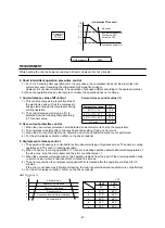


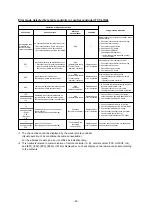


Contents Error Display
*
When the errors were overlapped, the latest error is displayed.
*
When D800 to D804 are slowly flashing or D805 is flashing, push and hold SW01 and SW02 simultaneously
for 5 seconds or more. The error display changes to the error which is generated.
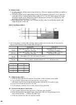
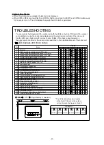
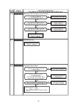
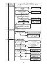
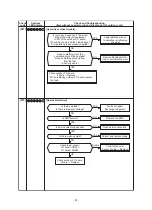
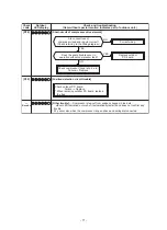
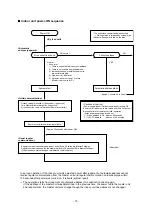
TROUBLESHOOTING
You can perform fault diagnosis of the outdoor unit with the LEDs on the Sub P.C.Board of the outdoor
unit in addition to using the check codes displayed on the wired remote controller of the indoor unit.
Use the LEDs and check codes for various checks. Details of the check codes displayed on
the wired remote controller of the indoor unit are described in the Installation Manual of the indoor unit.
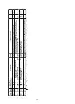
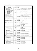
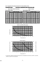
LED displays and check codes
1
2
3
4
5
6
7
8
9
10
11
12
13
14
15
16
17
18
19
20
21
22
23
24
25
Normal
Discharge temperature sensor (TD) error
Heat exchanger temperature sensor (TE) error
Heat exchanger temperature sensor (TL) error
Outside temperature sensor (TO) error
Suction temperature sensor (TS) error
Heat sink temperature sensor (TH) error
Miss-mounting of sensor (TE, TS)
EEPROM error
Compressor breakdown
Compressor lock
Current detection circuit error
Case thermostat activated
Unset model type
Communication error between MCUs
Discharge temperature sensor error
High pressure SW error
Power supply voltage error
Heatsink overheating error
Gas leak detected
4-way valve reversal error
High pressure protective activated
Fan system error
Compressor driver device short circuit
Position detection circuit error
: ON,
: ON
: ON, : OFF, : Ra
pid flashing (5 times/sec.)
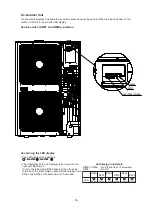
* The LEDs and switches are located
at the Sub P.C.Board of the outdoor
unit as shown in the figure on the left.
No.
Error
Display
D805
(Green)
D804
(Yellow)
D803
(Yellow)
D802
(Yellow)
D801
(Yellow)
D800
(Yellow)
LED displays
LED displays
Service Switches
D800
D801 D803 D805
D802 D804
SW01
SW02
1115284101
D801 D802 D803 D804 D805
D800
- 61 -