Toshiba XXXXXXX(<SanSerif1>X/X)
6
EN
Outdoor Unit
Installation Manual
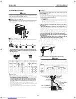
Charging Refrigerant
• You need not add refrigerant if the piping length is 40m or less.
• If the length exceeds 41m, add 20g of refrigerant per 1 meter over.
Procedure to Charge Refrigerant
After extraction is complete, close the valves, then charge the refrigerant.
• Make sure that no operations are in progress while charging the
refrigerant.
If you cannot charge the refrigerant fully, add it from the service port of the
service valve at the gas end while cooling operation is in progress.
NOTE
•
Charge the refrigerant in a liquid state.
• If you charge the refrigerant in a gas state, the air conditioner will not
operate properly since the refrigerant undergoes a change in its
composition.
Precautions for Adding Refrigerant
• Use a scale with a precision of at least 10 g per index line when adding the
refrigerant.
Do not use bathroom scales or similar instruments.
• Use liquid refrigerant when refilling.
Since the refrigerant is in liquid form, it can fill up quickly.
Therefore add the refrigerant gradually.
CAUTION
This product contains fluorinated greenhouse gases covered by the Kyoto
Protocol.
• Chemical Name of Gas : R410A
• Global Warming Potential (GWP) of gas : 1975
1. Stick the enclose refrigerant label adjacent to the charging and/or
recovering location.
2. Clearly write the charge refrigerant quantity on the refrigerant label using
indelible ink.
3. Prevent emission of the contained fluorinated greenhouse gas.
Ensure that the fluorinated greenhouse gas is never vented into the
atmosphere during installation, service or disposal.
If any leakage of the contained fluorinated greenhouse gas is detected, the
leak must be stopped and repaired as soon as possible.
4. Only qualified service personnel are allowed to access and service this
product.
5. Any handling of the fluorinated greenhouse gas in the product, such as
when moving the product or recharging the gas, must comply with (EC)
Regulation No.842/2006 on certain fluorinated greenhouse gases and any
relevant local legislation.
6. Contact dealers, installers, etc., for any questions.
Periodical inspections for refrigerant leaks may be required depending on
European or local legislation.
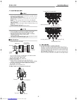
Insulation of the Refrigerant Pipes
• Insulate the refrigerant pipes for liquid and gas separately.
Gas Leak Inspection
• Perform a gas leak inspection for the flare nut connections, valve stem
connection, and service port cap without fail.
• Use a leak detector exclusively manufactured for R410A.
Performing Additional Installation of an Indoor Unit
1. Collect refrigerant from the outdoor unit.
2. Turn off the circuit breaker.
3. Perform additional installation referring to the procedure from "Refrigerant
Piping Connection" on the previous page.
Pump-down Operation (Recovering refrigerant)
CAUTION
Since the forcible running for collecting refrigerant stops automatically after
10 minutes, finish collecting refrigerant within 10 minutes.
Electric current is applied on the control board. Beware of
electric shock.
•
The following must be certainly done during pump down.
•
Do not incorporate air into the refrigeration cycle.
•
Close the 2 service valves. Stop the compressor and remove the
refrigerant pipe.
If the refrigerant pipe is removed when the compressor is operating and
service valves are opened, the refrigerant cycle will inhale unwanted
matter such as air and the pressure in the cycle becomes abnormally
elevated. It may cause a burst or injury.
1. Detach the front panel.
Do not remove the air discharge grille.
2. Connect the charge hose to the service port.
3. Turn on the power.
4. Start running all the indoor units connected to the outside unit in the cooling
mode.
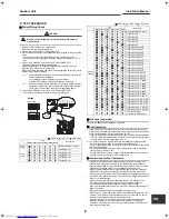
5. Press the SW800 button on the P.C board MCC 5071 for 10 to 60 seconds
to start the indoor unit(s) in the cooling mode forcibly.
• When the status of each LED changes to that shown on the "While holding
a button (10 to 60 seconds)" row on the table below, release the button.
The status of each LED on the P.C board MCC 5071 changes.
6. Close the valve stem of the service valve at the liquid end.
7. Make sure that the compound pressure gauge reading is –101kPa
(–76cmHg).
8. Close the valve stem of the service valve at the gas end.
9. Stop running all the indoor units.
R410A
kg
kg
kg
Pre-charged Refrigerant at Factory [kg],
specified in the nameplate
1
Additional Charge on Installation Site [kg]
2
Underground piping: 10t
(Laying the pipes on the wall,
ceiling, or under the floor)
Heat-proof bubble polyethylene
: LED ON, : LED OFF, : LED Flash
LED
D800
D801
D802
D803
D804
D805
Normal operation
While holding a button
(0 to 10 seconds)
While holding a button
(10 to 60 seconds)
Release a button
Flare nut connections
(Indoor unit)
Service port cap
connection
Valve stem cap
Flare nut connections
(Outdoor unit)
D800
D801
D802
D803
D804
D805
SW800
LED
+00EG44206701_01EN.book Page 6 Tuesday, July 20, 2010 9:32 PM
Содержание RAS-5M34UAV-E1
Страница 10: ...EG44206701 ...


