8-1.
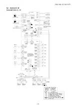
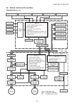
Outdoor Unit (Inverter Assembly)
RAS-
4
M
27
S3AV-
A
8. CONTROL BLOCK DIAGRAM
A unit P.M.V.
• Inverter outdoor frequency control
• A/D converter function
• P.M.V. control
• Processing (Temp. processing)
• Error display
• Serial signal communication with indoor unit
• Signal communication with main P.C. board
• Function select
M.C.U
Discharge temp. sensor
Gas side pipe temp. sensor
Suction temp. sensor
Evaporator temp. sensor
Outdoor air temp. sensor
MCC-5071 (CONTROL P.C. B)
MCC-1571 (MAIN P.C. B)
220
⎯
240V ~50Hz
220V ~60Hz
Driver
circuit of
P.M.V.
B unit P.M.V.
C unit P.M.V.
D unit P.M.V.
Demand
signal
Relay circuit
4-way valve
Function
select
P.M.V : Pulse motor valve
PWM : Pulse width modulation
IPM : Intelligent power module
Signal communication
Noise filter
MCC-1653
(Demand P.C.B)
Transformer
High power factor
correction circuit
Converter
(AC
→
DC)
Gate drive
circuit
Inverter
(DC
→
AC)
Converter
(AC
→
DC)
Output current
sensor
Output current
sensor
Input current
sensor
D unit serial signal
communication circuit
C unit serial signal
communication circuit
B unit serial signal
communication circuit
A unit serial signal
communication circuit
Clock frequency
oscillator circuit
20 MHz
Clock frequency
oscillator circuit
20 MHz
Gate drive
circuit
Inverter
(DC
→
AC)
•
Signal communication with
control P.C. board
• 4-way valve control
M.C.U 2
• PWM synthesis function
• Input current release control
• IPM over current detect control
• High power factor correction control
• Signal communication with
control P.C. board
• Fan motor control
• Compressor motor control
M.C.U 1
Compressor
Outdoor
fan motor
Clock frequency
oscillator circuit
8 MHz
High-pressure switch
Case thermo
•
High pressure protective operation.
•
Case thermostat operation.
FILE NO. SVM-15073
- 48 -
Содержание RAS-4M27S3AV-A
Страница 36: ...5 1 Outdoor Unit RAS 4M27S3AV A 5 WIRING DIAGRAM FILE NO SVM 15073 36 ...
Страница 112: ......


