


FILE NO. SVM-05015
– 74 –
Table 9-8-2 Approximate resistance value of thermo sensor
Temperature
0°C
10°C
20°C
25°C
30°C
Resistance value
35.8
20.7
12.6
10.0
7.92
(k
Ω
)
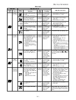
No.
Procedure
Check points
Causes
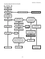
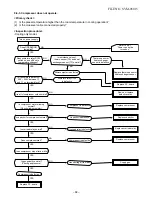
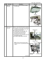
6
If the above condition (No. 6) still
continues, start the unit in the
following condition.
• Set the operation mode to HEAT.
• Set the preset temperature much
higher than room temperature.
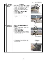
7 Connect the motor connector to the
motor and turn on the power supply.
Start the unit in the following
condition.
• Set the operation mode to FAN.
• Set the fan speed level to HIGH.
(The unit (compressor) operates
continuously in the above
condition.)
1. Check whether or not the
compressor operates.
2. Check whether or not the
OPERATION lamp blinks.
1. Check it is impossible to detect
the voltage between
2
and
3
of
the CN11.
2. The motor does not operate.
(But it is possible to receive the
signal from the remote control.)
2. The motor rotates but vibrates
strongly.
1. The temperature of the indoor
heat exchanger is extremely high.
2. The connector of the heat ex-
changer sensor short-circuited.
(CN01)
3. The heat exchanger sensor and
the P.C. board are defactive.
(Refer to Table 9-8-2.)
4. The main P.C. board is defective.
1. The indoor fan motor is defective.
(Protected operation of
P.C. board)
2. The connection of the motor
connector is loose.
3. The P.C. board is defective.
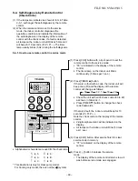
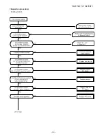
9-8-2. How to Shorten Time of Restart Delay Timer
1
Press [CLR] button while pressing [CHK] button
with a tip of a pencil.
2
Then press [ ] button to transmit the
signal to the indoor unit.
2
1


